SP-7XE/F Full-Rise Scissor Lift 42 P/N 5900010 — Rev. B3 — September 2023
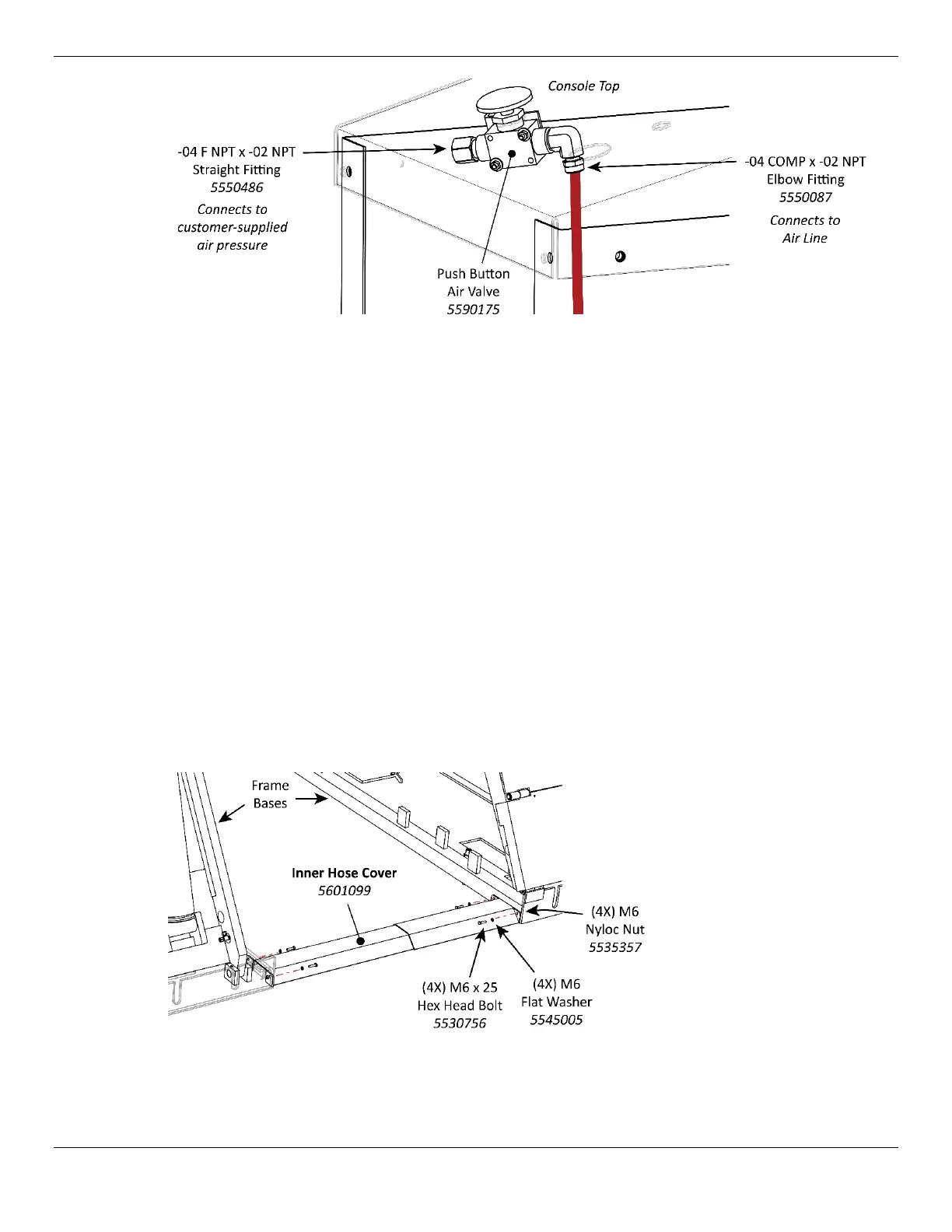
Pushbutton is above the Console Top; all other components are under the Console Top.
6. On the underside of the Console Top, attach the male end of a Straight Pipe Fitting to the IN
connector on the underside of the Pushbutton Air Valve, then connect the customer-supplied air
pressure to the other end of the Straight Pipe Fitting.
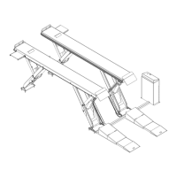
Install the Hose Covers
The Hose Covers are required to protect the Hydraulic Hoses and Air Line from damage.
The Inner Hose Cover is positioned between the Frame Assemblies; the Hose Cover is adjustable
40 – 46 inches / 1,016 – 1,168 mm.
The Outer Hose Cover is positioned between the Console and the closest Frame Assembly; it is not
adjustable for length. The Outer Hose Cover measures 40.25 in. / 1,022 mm long.
To install the Hose Covers:
1. Locate the Inner and Outer Hose Covers, eight M6 Hex Head Bolts, M6 Flat Washers, and M6
Nyloc Nuts.
2. Position the Inner Hose Cover between the Frame Assemblies, making sure to cover the Hydraulic
Hoses and Air Line, and then secure it to the Frame Bases using four M6 Hex Head Bolts, M6
Washers, and M6 Nuts.
⚠ CAUTION Use care to not crush or pierce the Hydraulic Hoses and Air Line underneath the
Hose Covers.