DANGER
Caution
Make sure that there is no electrical charge exists on the circuit
under test.
Make sure to put on a pair of insulated gloves for high voltage.
Do not take measurement when thunder rumbling.
Do not take measurement if the battery cover removed.
Do not take measurement when the live circuit waring is active.
-13- -14-
CLEAR
LINE
CAT.Ⅲ
600V
EARTH GUARD
LOCK
PRESS TO TEST
TIMER
SET
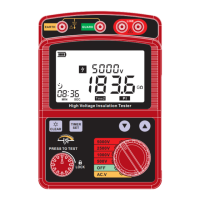
5000V
2500V
1000V
500V
AC.V
OFF
0
O
D
I
S
C
T
H
U
A
A
R
G
E
CLEAR
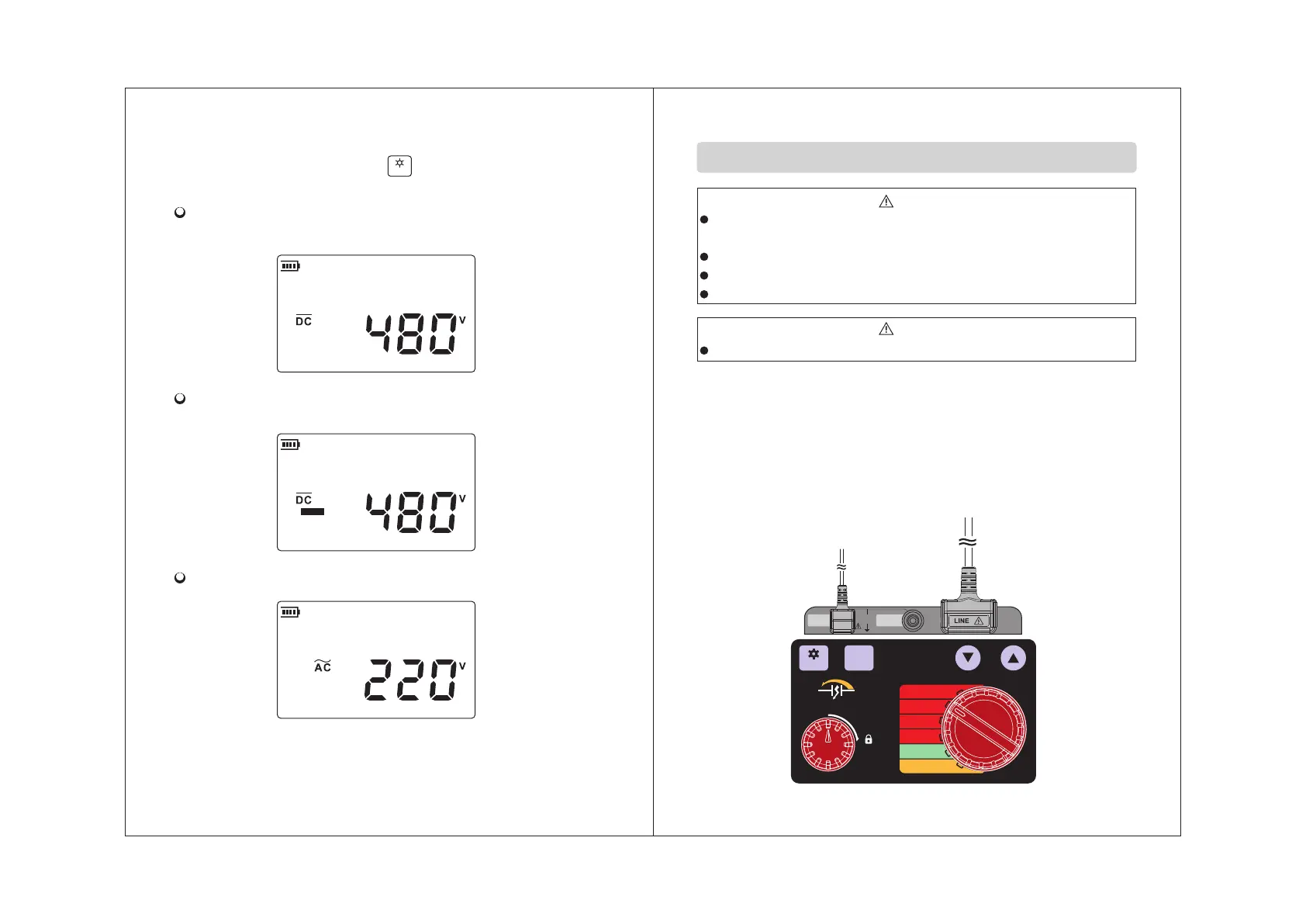
3. Connect the red or black test pin to the pole, if the beam
is dim you can press the “ ” button to turn on back
light. The LCD display shown as below:
Connect the red pin which test direct voltage to +,
connect the black to -, LCD display as below:
Connect the red pin which test direct voltage to-, connect
the black to +, LCD display as blow:
LCD display as blow when test AC:
4. Remove the test pin after measurement.
Then set the function switch to OFF position.
red
test wire
black
test wire
Insulation resistance measurement
1. Connect the red test wire and black test wire to reciprocal
terminal socket.
2. Setting the function switch to proper position according
to the content of insulation material, (you can take a try
follow the sequence 500V/ 1000V/ 2500V/5000V if you
do not know the resistance range) for example, 2500V: