9
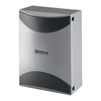
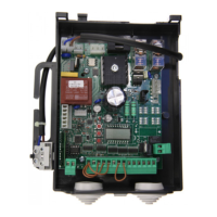
BRAIN control unit
The BRAIN electronic control unit may be used for the control of 1 or 2 motors with power not higher than 500W+500W.
GENERAL WARNINGS
a) The electrical installation and the operating logic must comply with the regulations in for
ce.
b) The leads fed with different voltages
must be physically separate, or they must be suitably insulated with additional insulation of
at least 1 mm.
c) The leads must be secured with an additional fixture near the terminals.
d) Check all the connections again before switching on the power.
e) The unused N.C. inputs must be bridged.
INPUT/OUTPUT FUNCTIONS
BRAIN Control unit
N° Terminals Function Description
1-2-3 Power supply Input 230Vac 50Hz (1-GND/2-Phase/3-Neutral)
4-5-6 Motor 1 Connection of motor 1: (4-start/5-Com/6-start)
7-8-9 Motor 2 Connection of motor 2: (7-start/8-Com/9-start)
10-11 Blinking light Connection of blinking light 230Vac 40W max.
12-13 TLS
N.O. clean contact for courtesy light, timer, etc.
The activation time is regulated by the parameter TLS
14-15 24 Vac Accessories power supply output 24Vac/0.5A max.
16-17 Lock 12Vac Accessories power supply output 12Vac/10W for electric lock (16:0V, 17:+12V)
18-19 SCA N.O. clean contact for gate open warning light.
20-21 EDGE
Input, sensitive edge contact
Resistive edge: “DAS” Jumper closed
Mechanical edge: “DAS” Jumper open
When the edge is activated, the gate movement is stopped and reversed for about 3s.
22 SWO-M1 OPEN limit switch input motor 1 (N.C contact.)
23 SWC-M1 CLOSE limit switch input motor 1 (N.C. contact)
24 SWO-M2 OPEN limit switch input motor 2 (N.C. contact)
25 SWC-M2 CLOSE limit switch input motor 2 (N.C. contact)
26-27 COM Common for limit switch and all the control inputs.
28 Step-by-Step Step-by-Step button input (N.O. contact)
29 PED Pedestrian button input (N.O. contact)
30 OPEN OPEN button input (N.O. contact), configurable as Clock contact
31 CLOSE CLOSE button input (N.O. contact)
32 PHOT Active photocell input on opening and closing
33 PHOT CLOSE Active photocell input only on closing
34 STOP STOP button input (N.C. contact)
35-36 Antenna
Antenna connection for plug-in radio receiver board (35-screen/36-signal).
37-38 RX 2ch.
Second radio channel output of the plug-in receiver.
Voltage-free N.O. contact.
J3 Radio Plug-in connector for radio receiver.
Notes:
The EDGE must be connected exclusively to the special inputs 20/21. Two types of EDGE may be used:
If an edge with resistance 8K2 is used, close the Jumper “DAS”.
If a mechanical edge with N.C. contact is used, open the Jumper “DAS”.
If the edge is not used, bridge the terminals 20-21 and open the Jumper “DAS”.