17
Fitting onto the limit switch brackets
The bases are complete with hooking tongue allowing the fitting of the magnets to the limit switch bracket supplied with the operator, as shown in Fig.14-B.
This type of fitting allows to rapidly adjust the position of magnets. After calculating the correct distance, fix the support in the correct position by means
of a screw, so as to avert the moving of the bracket.
Fitting onto the rack
As an alternative, the supports can be fitted directly to the rack, by using the slots shown in Fig. 14-C. This fitting mode does not allow for subsequent
regulations. It is therefore advised to make some trials with temporarily fitted supports before carrying out the final fitting.
IMPORTANT: The correct distance of the magnet with respect to the sensor depends on the installation characteristics. This space cannot be preset
and must be adjusted on a trial basis.
The distances regarding the triggering of the sensor (value X) with respect to distance K of 3 and 35 mm, which are shown in Fig. 14 are only indicative.
In any case, distance K must not exceed 35 mm as a higher distance will not allow the triggering of the magnetic sensor.
11) BUFFER BATTERIES (fig.15)
An optional kit of buffer batteries is available. This permits the operation of the system also in case of power failure.
The batteries can be installed inside the gear motor as shown in Fig.15.
The support of the control unit has a hole “Fig.15 ref. "A" which facilitates passage of the battery cables.
For further information, please see instructions supplied with the product.
12) WIRE DIAGRAM (fig.16)
For the wire connections of the system and to adjust the operating modes, please refer to the Instruction Manual of the control unit.
In particular, the anti-crash device (encoder) should be adjusted according to regulations in force.
Please remember that the device should be earthed by means of the appropriate terminal.
Fig.16 shows wiring for a standard installation. Before proceeding to wiring, check that the type of cables used is consistent with those required for ac-
cessories.
Dimension H stands for the installation height of photocells. A clearance between 40 and 60 cm is advisable.
Key of components:
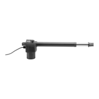
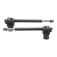
1 Gear motor with incorporated BULL control unit
2 M4 rack, Nylon/Fe
3 Limit switch brackets
4 Photocells
5 Mechanical stoppers
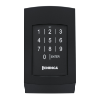
6 Key selector or digital keyboard
7 Flashing light
8 Antenna
13) CONTROL UNIT CP.B24-SW ELECTRICAL CONNECTIONS
The following table shows the electrical connections in Fig. 17:
Terminals Function Description
SEL 115/230 Mains power supply selection
230 Vac 50/60 Hz (from 207 to 253 Vac) jumper M7 OPEN
115 Vac 50/60 Hz (from 102 to 125 Vac) jumper M7 CLOSED
L/N/GND Power supply Mains power supply input 115Vac/230Vac selectable via M7 jumper
MOT Motor Quick connector for the connection of 24 Vdc motor
COM/SWO/SWC Adjustable
Quick connector for the connection of the limit switches
COM: Common - SWO Limit Switch Opens (N.C. contact) - SWC Limit switch closes
(N.C. contact)
ANT/SHIELD Antenna
Built-in radio receiver antenna connection
ANT: Signal / SHIELD: Display
COM General Common for all control inputs.
S.S. Step-by-Step
Step-by-step key input (N.O. contact).
The control unit executes a command at each S.S. impulse according to the sequence:
OPENS>STOP>CLOSES>STOP>OPENS or OPENS>CLOSES>OPENS.
See dip switch 2
STOP STOP
STOP key input (N.C. contact)
Settable as a PED key (N.O. contact) see dip switch 2
PHOT Photocell
Photocell input (N.C. contact) active in the closure and opening phase according to
the setting of dip switch 2
BLINK Flashing 24Vdc flashing connection 15W max.
+ 24V - 24 Vac/dc Power supply output accessories 24Vdc/500mA max.
AUX Auxiliaries output
Clean contact (N.O.) configurable using Dip Switch 1 as SCA (gate open indicator
light) or second radio channel.
J6 X.BE Quick connector for KNX interface card (item X.BE - See paragraph KNX)
M6 Battery charger Quick connector for optional battery charger card connection.
14) ARC TRANSMITTERS
IMPORTANT, PLEASE READ CAREFULLY:
The radio receiver in this product is compatible only with ARC (Advanced Rolling Code) transmitters which, thanks to 128 bit coding, guarantee superior
anti-copying security.
 Loading...