16
2) GENERAL INFORMATION
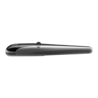
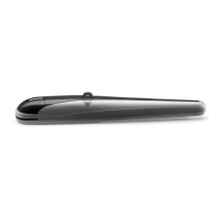
Automatic system, with 24 VDC single-phase power supply for sliding gates, for gates with maximum weight equal to 600 kg.
BULL is a monobloc system featuring a refined design and reduced dimensions. The motor and an irreversible reduction system, manufactured with high
resistant materials, are housed in an aluminium container. BULL is equipped with spring limit switches. The customised key emergency release allows
to open and close the gate in case of power failure.
Anti-crash safety is ensured by an electronic device (encoder and amperometric sensor) which detects any obstacle present.
3) PRELIMINARY CHECKS
For a good operation of the automatic system for sliding gates, the gate or door shall meet the following features:
-
the track and relevant wheels must feature correct sizes and must undergo adequate maintenance (in order to avert excessive friction during the sliding of the gate).
- during operation, the door shall not excessively oscillate.
- a mechanical stopper (according to regulations in force) shall limit the opening and closing movements.
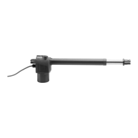
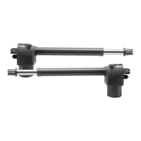
4) INSTALLATION (fig.1)
Overall dimensions of the gear motor expressed in mm.
5) POSITIONING OF THE FOUNDATION PLATE (FIG.2-3-4-5)
It is very important to keep to dimension X shown in Fig.2. This value depends on the type of rack used:
X = 52 mm for rack in nylon
X = 49 mm for rack in iron, 12x30mm
Preset a corrugated tube (Fig.2 -A) for the passage of power supply cables and connection wires for the accessories.
Check that, at the end of the fitting, the foundation plate is perfectly parallel with respect to the wing.
Fit the system with screw anchors on the bottom of the cement (Fig.3).
Drill 4 holes, diam.10mm, by using the foundation plate as drilling template.
Tightly anchor the foundation plate to ground through the 4 “T” steel screw anchors and the 4 “B” threaded bars, M8x150mm and corresponding “D”
nuts and “R” washers.
Alternative fitting systems are available on the market, e.g. anchoring with retaining expansion band (Fig.3 -T2) to be inserted in the hole with some ham-
mer strokes.
Fitting to be cemented (Fig.4)
In this case, after providing an adequate foundation hole, bend the threaded bars as shown in Fig.4.
Submerse the bars in cement, paying attention to the level of the plate.
Wait that the cement hardens.
Fig. 5 shows the completed fitting plate.
Regardless of the type of fitting, check that the threaded bars are firmly anchored to ground and that they protrude for at least 24mm (44 mm
for raised installation).
6) FITTING OF THE RACK (fig.6-7-8)
Rack in nylon (Fig.6).
Position the rack at a height of 68 mm from the centre line of the fixing slot provided on the base on which the foundation plate will be fitted. At that
height, drill a hole on the gate and provide for a M6 threading.
Keep to the P tooth pitch, even from a section of rack and another. To this purpose, it could be useful to join another section of rack (Part. C)
Rack in Fe 12x30mm (Fig.7).
Position the spacers D by welding them or fitting them with screws to the gate, at 103 mm height from the centre line of the fixing slot provided on the
base on which the foundation plate will be fitted. Fix the rack by following points 4.3 and 4.4.
Keep to the P tooth pitch, for all sections of the rack. To this purpose, it could be useful to connect another section of rack (Part. C)
Then fix the rack with V screws, taking care, once the actuator is installed, that 1-mm backlash is left between the rack and the tow wheel (seei Fig.8).
To this purpose, use the slots on the rack.
7) POSITIONING AND ANCHORING OF THE ACTUATOR (fig.9-10)
Position the gear motor on the foundation plate with the gear centred with respect to the rack.
Release the automatic system and check that the gear be correctly positioned along the entire stroke of the rack. If required, adjust the alignment by
using the special slots.
Fix the gear motor to the base by firmly tightening the 4 nuts D and inserting the R.
Apply the two screw covers C.
If the rack is already installed in a position which is higher than the pinion, the plate can be raised (20 m maximum) by moving the nuts and the washers
under the plate, as shown in Fig.10.
If the connecting cables already present make it difficult to fix the standard plate, the optional plate BULL P3 (Fig. 11) can be used, thus allowing to raise
the actuator installation by about 34 mm and facilitating the passage of cables.
8) POSITIONING OF THE LIMIT SWITCH BRACKETS (fig.12)
Manually open the gate and leave a clearance from 1 to 3cm according to the weight of the gate between the main door and the mechanical stopper
A. Fix the bracket to the limit switch S by using the grains G, so that the limit switch microswitch F is pressed. The same operation should be repeated
with gate in the closing phase.
N.B.: The limit switch bracket should be positioned so that the gate can be stopped without hitting the mechanical stopper.
9) MANUAL OPERATION (fig.13)
Should a power failure or malfunction occurs, to manually operate the gate proceed as follows:
- After inserting the customised key C, turn it anti-clockwise and pull the lever L.
- The gear motor is unlocked and the gate can be moved by hand.
- To return to the normal operating mode, close the lever L again and manually activate the gate until it is geared.5.4)
10) HOW TO INSTALL THE MAGNETS (BULL424 SW.S - fig.14)
The magnets are housed in special supports (fig.14-”A”). These magnets are to be fitted to the limit switch brackets or the rack and cause the triggering
of sensors when they approach them.
 Loading...