13
CONTROL PANEL CP.B24 ESA / CP.B1024 ESA
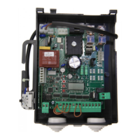
WIRE DIAGRAM
Wire connections shown in Fig. 1 are described hereunder:
Terminals Function Description
L/N Power supply
Input, 230VAC 50/60 Hz (L-Phase/N-Neutral) CP:B24ESA/CP-B1024ESA
Input, 115VAC 50/60 Hz (L-Phase/N-Neutral) CP:B24ESA/CP-B1024ESA-A
L1/N1
Primary
Transformer
Connector for the connection of the primary transformer
L1: Line
N1: Neutral
0V/MOT/AUX
Secondary
Transformer
Connector for the connection of the secondary transformer
CP.B24ESA: 0V: 0V Input - MOT:23 VAC - AUX:18 VAC
CP.B1024ESA: 0V: 0V Input - MOT:30 VAC - AUX:18 VAC
MOT Motor Fast connector for motor connection
ENC Encoder Fast connector for encoder connection
COM
SWO
SWC
Limit Switches
Rapid connector for the connection of limit switches.
COM:Common for limit switches
SWO:Input, OPEN limit switch (N.C. contact)
SWC:Input, CLOSE limit switch (N.C. contact)
BAR/BAR
SAFETY
EDGE
Input: sensitive safety edge
8K2 resistive safety edge: closed “DAS” jumper
Mechanical safety edge: open “DAS” jumper
When the safety edge is activated, the gate leaf stops and its movement is reversed for around
3 seconds.
PED PEDESTRIAN
Pedestrian push-button intput (N.O. contact). The gate partial opening is controlled
according to the value preset by the TPED parameter.
It is activated only with totally closed gate.
With OPCL:ON or HTR:ON, it becomes “CLOSE” input.
PHO
Open
Photocell
Input, photocell activated in both opening and closing phases
PHC Photocell Input, photocell is activated in the closing phase.
STOP STOP STOP button input (N.C. contact)
P.P. Step by step
Input, Step-by-Step push-button (Normally Open contact)
If the logics is OPCL=ON or HTR=ON, the OPEN input function is provided.
If the logics HTR is ON, it is FORBIDDEN to use the input with timers or other similar
systems.
+COM COMMON Common for all control inputs.
SHIELD/ANT antenna
Connection antenna to the built-in receiver
SHIELD: Screen / ANT: Signal
+ 24V - 24 Vdcs Accessories power supply 24Vdc/500mA max.
TECHNICAL DATA
Contol unit power supply
24 Vdc
Power supply
230 Vac 50/60 Hz or 115Vac 50/60Hz according to the version
Output
1 motor 24Vdc
Maximum current:
CP.B24ESA: 2.8 A - CP.B1024ESA: 3.5 A
Accessories power supply
24Vdc 500mA max.
Protection level
CP.B24ESA:IP30 - CP.B1024ESA:IP20
Operating temp.
-20°C / +50°C
Radio receiver
built in 433,92 MHz confgurabile (rolling-code or programmable + rolling-code+ ARC
Advanced Rolling Code)
Memory capacity
64 rolling-code transmitters
 Loading...