7
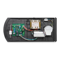
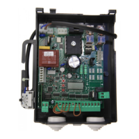
Control units CP.K
Control units for 24Vdc motors with powers under 120W.
GENERAL RULES
a) The electrical installation and operating logic must comply with statutory regulations.
b) Cables of different voltages must be physically separated or otherwise adequately screened with
secondary insulation of at least 1 mm.
c) Cables must be secured by additional clamps next to their terminals.
d) Control all wiring connections are correct before powering.
e) Check the Dip-Switch settings are correct.
f) Unused N.C. inputs must be jumpered.
INPUT/OUTPUT FUNCTIONS
Terminals Function Description
(1-2) Antenna
Optional antenna connection to built-in radio receiver board (1-
signal/2-screen).
If external antenna connected cut wire welded to “ANT”.
5 COM Common for all control inputs.
6 Step by Step Step by step button input (N.O. contact)
7 STOP STOP button input (N.C. contact)
8 PHOT
Input for safety devices, N.C. contact (e.g. photocells)
In close cycle: if the contact opens, the motor will stop and will in-
stantly reverse direction (opening).
In open cycle: disabled.
JP7 24Vdc Motor Jack for 24Vdc motor
JP10 Limit switch
Jack for limit switches:
A: SWC – Close limit switch
B: SWO – Open limit switch
C: COM – Common for limit switches
14-15 Blinker Blinker connection, 24Vac/15W max.
16-17 24 Vac Accessory power supply 24Vac/1A max.
JP4 Secondary
Secondary circuit of the transformer.
18 Grey: 0V output
19 Red: Slowdown speed.
Connect the Faston to the 15V output (minimum slowdown
speed) or 20V (maximum slowdown speed).
20 Brown: 24V output
21 White: Motor speed.
Connect the Faston to the 20V output (minimum motor speed)
or 30V (maximum motor speed).
See section “Motor speed adjustment ”
J3 Radio Receiver Built-in radio receiver
N.B.: To control the automation during installation, the Step by Step button on the control unit can be
used.
 Loading...