8
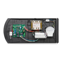
Control units CP.M24-RE / CP.M24-RI
Control units for 24Vdc motors with powers under 80W.
GENERAL RULES
a) The electrical installation and operating logic must comply with statutory regulations.
b) Cables of different voltages must be physically separated or otherwise adequately screened with
secondary insulation of at least 1 mm.
c) Cables must be secured by additional clamps next to their terminals.
d) Control all wiring connections are correct before powering.
e) Check the Dip-Switch settings are correct.
f) Unused N.C. inputs must be jumpered.
INPUT/OUTPUT FUNCTIONS
Terminals Function Description
1-2 Power 230Vac 50Hz input (1-Neutral/2-Live)
4-5 24Vdc motor 24Vdc motor connection
6-7 Beacon 24Vac max 15W beacon connection
8-9 24 Vac
24Vac/max 0.5A accessory power connection
IMPORTANT: If the battery charger board CB.24V is installed, the
output (without mains power connected) has a 24Vdc polarised
voltage. Make sure the devices are correctly connected.
(i.e. 8;+24Vdc - 9:-24Vdc).
10-11 SCA 24 Vac connection for gate open light – max 3W
12 COM Common for all control signal inputs.
13 STOP STOP button input (N.C. contact)
14 PHOT
Safety input, N.C. contact (e.g. photocells)
During closing: when the contact opens the motor is stopped and
the stroke direction is reversed immediately (i.e. opening).
In the opening phase: operation settable by Dip-switch 5.
15 OPEN OPEN button input (N.O. contact)
16 CLOSE CLOSE button input (N.O. contact)
17 PP Step-by-step Step-by-step button input (N.O. contact)
18 COM Common connection for travel limit switches.
19 PED
PEDESTRIAN button input (N.O. contact)
It opens for 7sec (1,5÷2m)
20 SWO OPEN travel limit switch input (N.C. contact).
21 SWC CLOSE travel limit switch input (N.C. contact).
24-25 Antenna
Plug-in radio receiver antenna board connections
(24-signal/25-screen).
26-27 EDGE
Edge contact input
Electric edge: Jumper “DAS” bridged
Mechanical edge: Jumper “DAS” open
When the sensitive edge is activated, the gate stops and its move-
ment is reversed for approx. 3s.
Edge not used: Jumper “DAS” open and jumper across terminals
26-27.
28-29 RX 2ch.
Output, second radio channel. N.O. contact, voltage free.
It is enabled with both xed receiver and expandable two-channel
receiver
J2 Radio receiver Socket for two channel radio receiver (“RE” versions)
The RI versions have a built-in radio receiver
0-VMOT Secondary Terminal for secondary circuit of transformer
 Loading...