TECHNICAL DATA
Contol unit supply
24 Vdc
Power supply
230 Vac 50/60 Hz or 115Vac 50/60Hz according to the version
Output supply
1/2 motor 24Vdc
Maximum motor current
2.5+2.5 A
Output supply accessories
24Vdc 500mA max.
Protection level
IP54
Operating temp.
-20°C / +70°C
Radio receiver
built in 433,92 MHz confgurabile (rolling-code or programmable + rolling-code)
Rolling code transmitters supported
64
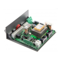
HEADY 24 CONTROL UNIT
AUTOSET FUNCTION
IMPORTANT: The control unit is equipped with the Autoset function to automatically set the main functioning values based on the
type of installation.
The AUTOSET function must be repeated at every function parameter change or upon change of automation conditions. See the
AUTO menu for further information.
WIRE DIAGRAM
Wire connections shown in Fig. 1 are described hereunder:
Terminal No.
Function Description
1-2 Motor 1 Connection, motor 1: 24VDC 2.5A max
3-4 Motor 2 Connection, motor 2: 24VDC 2.55A max
5-6 Flashing light Connection, flashing light 24VDC 15W max.
9-10
SCA/
PHOTO TEST/
2 CH
Normally Open, voltage-free contact, configurable as open gate indicator light, photocell
test or second radio channel (see Fig. 4).
For use as “Open gate indicator” the TEST1 and TEST2 logics must be OFF
For use as photocell test it is sufficient to activate one or both TEST logics and connect
the photocells as indicated in Fig.3.
11-12 24 Vac/dc
Output, accessory power supply, 24VAC/0.5A max.
IMPORTANT: If the battery charger board is installed, the output (without mains power
connected) has a 24Vdc polarised voltage.
Make sure the devices are correctly connected (i.e. 11:+24Vdc / 12:-0Vdc).
13-25 COM/ENC+ Common for limit switch and all the command inlets or encoder power supply.
14 SWO1/ENC1 Motor 1 OPEN limit switch input (N.C. contact) or Motor 1 Encoder connection.
15 SWC1 Motor 1 CLOSE limit switch input, (N.C. Contact)
16 SWO2/ENC2 Motor 2 OPEN limit switch input, (N.C. Contact) or Motor 2 Encoder connection.
17 SWC2 Motor 2 CLOSE limit switch input, (N.C. Contact)
18 PHOTO/BAR
Input, photocell activated in both opening and closing phases
As an alternative, the PHOTO input can be used to connect a safety edge (see BAR log-
ics).
19 PHOTC Input, photocell activated in closing phase only (Normally closed contact)
20 STOP Input, STOP push-button (Normally closed contact)
23 PED
Input, pedestrian push-button (N.O. (Normally Open) contact). It controls the total opening,
motor 1.
24 Step-by-Step Input, step-by-step push button (Normally open contact)
26 ENC- Input for GND Encoder connection (see Fig.2).
31-32 Antenna Connection to the built-in radio receiver card (31-signal/32-screen).
+ / - 24VAC/dc
Input, 24VAC/24VDC power supply.
In case of use of plug batteries connect the battery charging card as indicated in the specific
installation instructions.