16
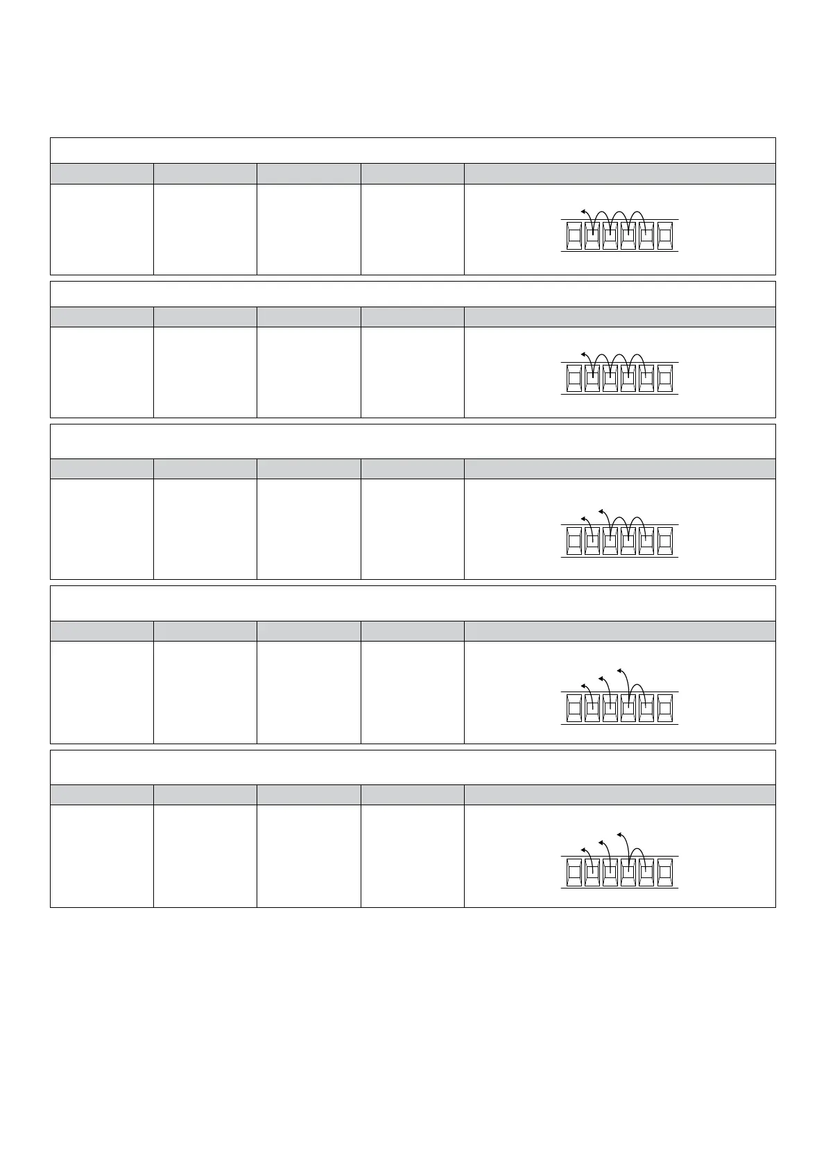
IMPORTANT: Photocell inputs not in use
All photocell inputs are short-circuited by default (PHOT1/2/3/4) with the COM terminal. With this presetting, the control unit can
be operated also without photocells.
After connecting and setting the photocells required by the type of system, the inputs which are not in use should be short-circuited
to the inputs in use by copying the settings in the PHOx parameter, as shown hereunder:
1 pair of photocells on input PHOT1, active in the closing phase only:
Logic PHO 1 Logic PHO 2 Logic PHO 3 Logic PHO 4 JUMPERS
ON ON ON ON
RX1
1 pair of photocells on input PHOT1, active in both opening and closing:
Logic PHO 1 Logic PHO 2 Logic PHO 3 Logic PHO 4 JUMPERS
OFF OFF OFF OFF
RX1
1 pair of photocells: active in both opening and closing (PHOT1)
+ 1 pair of photocells: active in the closing phase only (PHOT2):
Logic PHO 1 Logic PHO 2 Logic PHO 3 Logic PHO 4 JUMPERS
OFF ON ON ON
RX1
RX2
2 pairs of photocells, active in both opening and closing (PHOT1 e PHOT2)
+ 1 pair of photocells, active in the closing phase only (PHOT3):
Logic PHO 1 Logic PHO 2 Logic PHO 3 Logic PHO 4 JUMPERS
OFF OFF ON ON
18 2019 21
RX1
RX2
RX3
2 pairs of photocells, active only in the closing phase (PHOT1 e PHOT2)
+ 1 pair of photocells, active in both opening and closing phases (PHOT3):
Logic PHO 1 Logic PHO 2 Logic PHO 3 Logic PHO 4 JUMPERS
ON ON OFF OFF
18 2019 21
RX1
RX2
RX3