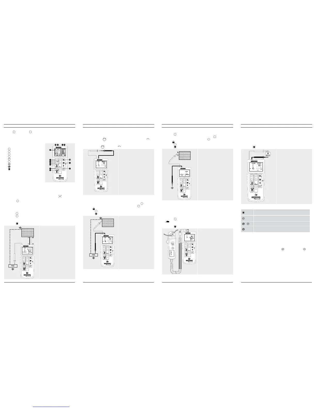
9. AC/DC voltage measurement
1. Disconnect the PV measuring leads from the BENNING PV 2.
2. Connect the red and black safety measuring lead as pictured.
3. The BENNING PV 2 automatically measures the AC/DC voltage at the measu-
ring probes.
4. The polarity of the DC voltage is displayed by “+/-“. In case of AC voltage, “+/-“
will be displayed alternately.
5. Press the -key
J
to store the measured values.
500V
250V 1000V
PV 2
DIN EN 62446 (VDE 0126-23), DIN EN 61829 (VDE 0126-24)
Auto Mode
a Vo/c, Is/c, MΩ
b Vmpp, Impp, FF
c a + b
d
Auto
Ω
NULL
R
PE
Mode
R
ISO
V
ISO
NULL
Max.
CAT III 400 V
10. Measured value memory (999 display screens)
-Store
Store all measurements currently on the LC display. In the RE-
CALL mode, the measuring results are called in reverse order.
-Recall
Recall the stored measured values on the LC display. Press
and hold to send the measured value memory to the USB port.
1
+
Clear all results from memory.
1
+Display
Switch-over of the LC display in the I-V characteristics mode
from Vo/c, Is/c to Vmpp, Impp.
11. Downloading the measured value memory to the PC
1. Install the BENNING SOLAR data logger and driver from the CD-ROM.
2. Disconnect all measuring leads from the BENNING PV 2.
3. Connect the BENNING PV 2 to your PC by means of the USB connecting cable.
4. Start the PC software, select the COM port and click “Download”.
5. Switch on the BENNING PV 2, press the -key
8
and hold the -key
8
again for approx. 2 seconds to start the download.
6. Open the measured value file in the CSV format via MS Excel
®
.
Note:
The optional PC software BENNING SOLAR Manager (part no. 050423) allows
documentation according to DIN EN 62446 (VDE 0126-23) as well as representa-
tion of the I-V characteristic according to DIN EN 61829 (VDE 0126-24).
7. Insulating resistance (R
ISO
, 2-pin)
1. Connect the 4 mm measuring leads as shown in the figure.
2. Press the
V
ISO
-key
7
to select an ISO testing voltage of 250 V, 500 V or 1.000 V.
3. For single measurement (2 sec.), press and release the
R
ISO
-key
4
.
For continuous measurement, press and hold the
R
ISO
-key
4
for several seconds
until the symbol is shown on the LC display
1
.
4. Press the
R
ISO
-key
4
to terminate the continuous measurement.
5. Press the -key
J
to store the measured values.
PV-module/ -string
500V
250V 1000V
PV 2
DIN EN 62446 (VDE 0126-23), DIN EN 61829 (VDE 0126-24)
Auto Mode
a Vo/c, Is/c, MΩ
b Vmpp, Impp, FF
c a + b
d
Auto
Ω
NULL
R
PE
Mode
R
ISO
V
ISO
red
black
Option:
40 m measuring leads BENNING TA 5
part no. 044039
8. AC/DC current measurement
1. Disconnect all measuring leads from the BENNING PV 2.
2. Connect the BENNING CC 3 (option) current clamp adapter to the 4 mm test
sockets.
3. Select the 40 A range on the BENNING CC 3.
4. Press the null balance key (ZERO) of the BENNING CC 3 for approx. 2 seconds.
5. Press the
Mode
-key
5
to select the desired mode
d
of the BENNING PV 2. The
symbol is shown on the LC display
1
.
6. The AC/DC current can be measured in single-wire live conductor.
7. Press the -key
J
to store the measured values.
500V
250V 1000V
PV 2
DIN EN 62446 (VDE 0126-23), DIN EN 61829 (VDE 0126-24)
Auto Mode
a Vo/c, Is/c, MΩ
b Vmpp, Impp, FF
c a + b
d
Auto
Ω
NULL
R
PE
Mode
R
ISO
V
ISO
+
40A : 10mV/A
300A : 1mV/A
BATT
LOW
PWR
ON
BENNING CC 3
ZERO A
OFF
40A
300A
CAT. III 600V
300A
Option:
BENNING CC 3
part no. 044038
5. Null balance of the measuring leads, resistance (R
PE
)
1. Connect the measuring leads to the red and black 4 mm test sockets of the
BENNING PV 2.
2. Short-circuit the probe tips via the alligator clips.
3. Press and hold the
Ω
NULL
-key
6
until an acoustic signal sounds and the
NULL
-symbol is removed from LC display
1
.
500V
250V 1000V
PV 2
DIN EN 62446 (VDE 0126-23), DIN EN 61829 (VDE 0126-24)
Auto Mode
a Vo/c, Is/c, MΩ
b Vmpp, Impp, FF
c a + b
d
Auto
Ω
NULL
R
PE
Mode
R
ISO
V
ISO
NULL
red black
Note:
Max. measuring lead resistance:
10 Ohm
6. Protective conductor resistance (R
PE
)
1. Connect the 4 mm measuring leads as shown.
2. To make a single measurement (2 sec.), press and release the
R
PE
-key
2
.
3. To make a continuous measurement, press and hold the
R
PE
-key
2
until the
symbol is displayed
1
continuously.
4. Press the
R
PE
-key
2
to terminate the continuous measurement.
5. Press the -key
J
to store the measured values.
500V
250V 1000V
PV 2
DIN EN 62446 (VDE 0126-23), DIN EN 61829 (VDE 0126-24)
Auto Mode
a Vo/c, Is/c, MΩ
b Vmpp, Impp, FF
c a + b
d
Auto
Ω
NULL
R
PE
Mode
R
ISO
V
ISO
NULL
R
PE
red
black
PV-module/ -string
Option:
40 m measuring leads BENNING TA 5
part no. 044039
2. Switching the device ON/OFF
Press the
R
ISO
-key
4
and the
Mode
-
key
5
simultaneously to switch the device ON or
OFF. Without pressing a key, the device switches OFF automatically after approx. 1
minute (APO, Auto Power-Off). The switch-off time can be set within a range from
1 min. to 10 min. (see operating manual on CD-ROM).
3. Device description
500V
250V 1000V
PV 2
DIN EN 62446 (VDE 0126-23), DIN EN 61829 (VDE 0126-24)
Auto Mode
a Vo/c, Is/c, MΩ
b Vmpp, Impp, FF
c a + b
d
Auto
Ω
NULL
R
PE
Mode
R
ISO
V
ISO
5
%
NULL
1
LC Display
2
R
PE
key, protective conductor test
3
Auto
-key, automatic test procedure
4
R
ISO
-key, insulation test (2-pin)
5
Mode
-key, selecting the test procedures
6
Ω
NULL
-key, null balance of the measuring line
7
V
ISO
-key, selecting the ISO testing voltage
8
-key, calling measured values
9
1
-key, switch-over of LC display
J
-Taste, storing measured values
K
+ PV test socket (red)
L
– PV test socket (black)
M – 4 mm test socket (black)
N + 4 mm test socket (red)
4. AUTO measurement of the PV generator
1. Connect the BENNING PV 2 to the PV generator as shown, by means of the
enclosed PV measuring leads and the red 4 mm test lead.
2. The open-circuit voltage (Vo/c) is automatically displayed.
3. In case of reversed polarity of the DC voltage, the symbol is displayed
1
and the measurement will be blocked.
4. Press the
Mode
-key
5
to select the desired test procedure (modes
a
-
d
):
a
Measuring Vo/c, Is/c and MΩ
b
Measuring the I-V characteristic with Vmpp, Impp and FF (filling factor)
c
Measuring
a
+
b
d
Measuring via AC/DC current clamp
5. Press the
V
ISO
-key
7
to select an ISO testing voltage of 250 V, 500 V or 1.000 V.
6. Press the
Auto
-key
3
to start the test procedure.
7. As soon as the test procedure is completed, “Store?” will be indicated on the LC
display
1
.
8. Press the -key
J
to store the measured values.
500V
250V 1000V
PV 2
DIN EN 62446 (VDE 0126-23), DIN EN 61829 (VDE 0126-24)
Auto Mode
a Vo/c, Is/c, MΩ
b Vmpp, Impp, FF
c a + b
d
Auto
Ω
NULL
R
PE
Mode
R
ISO
V
ISO
NULL
red red
black
PV-module/ -string
c
Attention:
Maximum DC power: P ≤ 10 kW,
Vo/c ≤ 1000 V, Is/c ≤ 15 A
Do not make measurements at PV
strings or PV inverter which are
connected in parallel!
Note:
The red 4 mm measuring lead is
required for the insulation resistance
measurement.
Measurement of the I-V characteristic
requires previous coupling to the
BENNING SUN 2.
12/ 2017
BENNING PV 2
512/ 2017
BENNING PV 2
412/ 2017
BENNING PV 2
312/ 2017
BENNING PV 2
2
 Loading...


