Short Instructions
BENNING PV 2
1. Important information
m
Before using the BENNING PV 2 please read the detailed operating
manual (CD-ROM) carefully.
The BENNING PV 2 should only be used by suitably trained per-
sonnel.
c
The connection to the PV generator is made exclusively in ac-
cordance with the connection figure of the operating manual.
Disconnect not required tests leads from the BENNING PV 2.
c
The PV module/PV string must not exceed the maximum opencir-
cuit voltage of 1000 V DC, the maximum short-circuit current of 15 A
and the maximum DC power (P = U x I) of 10 kW.
According to DIN EN 62446, the measurements have to be made
for each PV string. Measuring at PV strings connected in paral-
lel or contacting at the PV inverter might involve damages of the
BENNING PV 2!
c
Disconnect the BENNING PV 2 from the test sample directly after
the test.
c
Do not touch the measuring probes! During insulating resistance
measurements, high electric currents might be applied to the
measuring probes.
c
Do not touch any metal parts of the test object during measure-
ment.
c
The PV generator must be isolated from the electric power supply!
Neither the positive nor the negative pole of the PV generator must
be earthed!
c
Via the 4 mm test leads, voltage measurements on mains supply
circuits are possible. Via the 4 mm test sockets, the BENNING PV 2
must be used only in electric circuits of overvoltage category III
with max. 300 V AC/DC for phase-to-earth measurements. For this
please disconnect the PV 2 PV measuring leads from the PV test
sockets before measuring.
c
Before starting the unit, always check it for signs of damage. Do not
use a damaged BENNING PV 2!
m
Only use measuring leads, which are supplied with the
BENNING PV 2.
c
The BENNING PV 2 is intended for making measurements under dry
ambient conditions only.
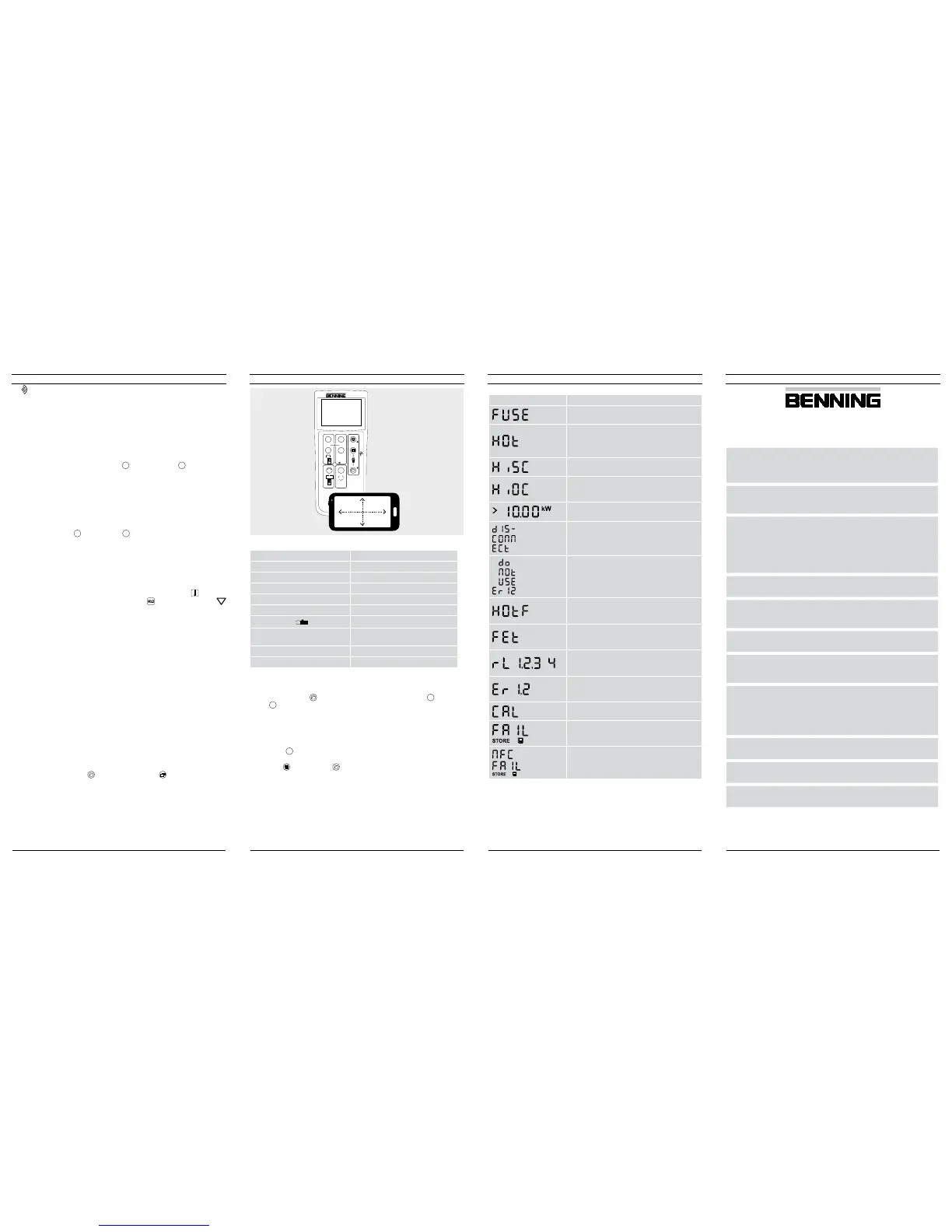
16. Error codes
Error code Remedy
The internal fuse has blown. Refer to chapter 9.5
in the opera ting instructions for details.
The electronic components of the BENNING PV 2
have reached the maximum admissible tempera-
ture. Disconnect the BENNING PV 2 from the ob-
ject to be measured and let it cool down.
The DC short-circuit current has the maximum va-
lue of 15 A. The measurement has been stopped.
The DC open circuit voltage has exceeded the
maximum value of 1000 V. The measurement has
been stopped.
The DC power has exceeded the maximum value
of 10 kW. Measurement has been cancelled.
Immediately disconnect the BENNING PV 2 from
the PV generator!
Please return the BENNING PV 2 to an authorized
service center, see chapter 9.6 „Calibration“ for
the address.
Please return the BENNING PV 2 to an authorized
service center, see chapter 9.6 „Calibration“ for
the address.
Please return the BENNING PV 2 to an authorized
service center, see chapter 9.6 „Calibration“ for
the address.
or
Please return the BENNING PV 2 to an authorized
service center, see chapter 9.6 „Calibration“ for
the address.
etc.
Please return the BENNING PV 2 to an authorized
service center, see chapter 9.6 „Calibration“ for
the address.
The BENNING PV 2 is not correctly calibrated,
see chapter 9.6 „Calibration“.
Storage has failed. Please store the measured va-
lues again to the next storage location available.
Storage to the NFC chip has failed. Please remove
the NFC-enabled device from the BENNING PV 2.
Other error codes see detailed user guide on CD-ROM.
17. Optional accessories
PC software BENNING SOLAR Manager (part no. 050423)
Temperature sensor with suction cup for BENNING SUN 2 (part no. 050424)
PV module holder for BENNING SUN 2 (part no. 050425)
Current clamp adapters BENNING CC 3 (part no. 044038)
Measuring lead BENNING TA 5, length 40 m (part no. 044039)
500V
250V 1000V
PV 2
DIN EN 62446 (VDE 0126-23), DIN EN 61829 (VDE 0126-24)
Auto Mode
a Vo/c, Is/c, MΩ
b Vmpp, Impp, FF
c a + b
d
Auto
Ω
NULL
R
PE
Mode
R
ISO
V
ISO
14. Measuring ranges and limiting values
Function Range
R
PE
/V 0.05 Ω - 199 Ω/30 V - 440 V AC/DC
R
ISO
(2-pin) 0.05 MΩ - 300 MΩ
Vo/c 5 V - 1000 V DC
Is/c 0.5 A - 20 A DC
R
ISO
(AUTO measurement) 0.2 MΩ - 200 MΩ
I
0.1 A - 40 A AC/DC
ISO test voltage
Limiting value of
insulating resistance
250 V 0.5 MΩ
500 V/ 1000 V 1.0 MΩ
15. Setting the date and time
1. Turn off the BENNING PV 2.
2. Press and hold the
-
key
8
and then press simultaneously the
R
ISO
-key
4
and
the
Mode
-key
5
of BENNING PV 2.
3. The date format and time format is shown as follows:
MM.DD = month (1-12). Day (1-31)
YYYY = year
HH.mm = hours (0-23).minutes (0-59)
SS = seconds (0-59)
4. Press the
R
PE
-key
2
to select a date field and time field
5. A blinking field shows that this field can be set.
6. With the -key
J
and the
-
key
8
, the value increases or decreases. With
each change, the second field is set to zero.
7. Turn off the device to save the setting.
Note:
If the BENNING PV 2 has established a radio connection to the BENNING SUN 2,
the date/ time of the BENNING PV 2 will be synchronized automatically after 10
seconds to the date/ time of the BENNING SUN 2, if the device detects a deviation
of more than 1 minute. BENNING SUN 2 (master) → BENNING PV 2 (slave).
12. Radio connection to the BENNING SUN 2
The BENNING PV 2 is able to receive the measured values (insolation, PV module /
ambient temperature and date / time stamp) of the optional BENNING SUN 2 (part
no. 050420) via radio connection.
Typical radio range in open space: approx. 30 m
Coupling with BENNING SUN 2
1. Remove all electronic devices in direct vicinity
2. Switch the BENNING PV 2 and the BENNING SUN 2 off.
3. Press and hold the two ON/OFF keys of the BENNING SUN 2.
4. Press and simultaneously hold the
R
ISO
-key
4
and the
Mode
-key
5
of the
BENNING PV 2.
5. The BENNING PV 2 indicates the successful coupling by means of an acoustic
signal and by displaying the serial no. of the BENNING SUN 2
6. The “W/m
2
” symbol is shown on the LC display
1
of the BENNING PV 2.
Decoupling from BENNING SUN 2
1. Remove all electronic devices in direct vicinity.
2. Switch the BENNING PV 2 off.
3. Press and hold the
R
ISO
-key
4
and the
Mode
-key
5
of the BENNING PV 2 for ap-
prox. 10 seconds.
4. The BENNING PV 2 indicates the decoupling from the BENNING SUN 2 by
means of an acoustic signal and by clearing the LC display.
5. The “R
PE
/Ω” symbol is shown on the LC display
1
of the BENNING PV 2.
Activating/deactivating the radio transmission of the BENNING SUN 2
1. Couple the BENNING PV 2 with the BENNING SUN 2.
2. To activate/deactivate the radio transmission, press and hold the -key of the
BENNING SUN 2 and simultaneously press the -key. A flashing triangle
is shown on the LC display.
3. The BENNING PV 2 receives the measured values as soon as the insolation
(W/m²) is shown on the LC display
1
.
4. AUTO measurement (modes
a
-
c
) additional stores the temperature values
and the date/time stamp of the BENNING SUN 2.
5. If the BENNING PV 2 is outside the radio range of the BENNING SUN 2, the “W/
m
2
” on the LC display
1
starts flashing. Moreover, “_ _ _ _” is shown on the LC
display, if the measured insolation value is outside the measuring range.
Note:
If the BENNING PV 2 does not receive any radio signal from the BENNING SUN 2, the
display indications are stored with the date/time stamp of the BENNING PV 2.
13. Representing the I-V characteristic via the “BENNING PV Link” app
Requirements: NFC-enabled Android device
The app allows the user to represent and to compare the measured I-V characte-
ristic and the power characteristic with the nominal module data of the manufacturer
under STC conditions.
Please read the detailed operating manual of the BENNING PV 2 and of the
“ BENNING PV Link” on the CD-ROM rst.
1. The NFC chip required for this functionality is located under the NFC logo on the
top of the BENNING PV 2 housing.
2. Upon completion of each test procedure (modes
b
+
c
) as well as after calling
a storage location via the -key
8
and pressing the
1
-key
9
, the I-V charac-
teristic is written to the NFC chip.
3. The I-V characteristic can be read and represented via an Android device with
NFC functionality.
12/ 2017
BENNING PV 2
112/ 2017
BENNING PV 2
812/ 2017
BENNING PV 2
712/ 2017
BENNING PV 2
6
 Loading...


