The Control Panel and its Components
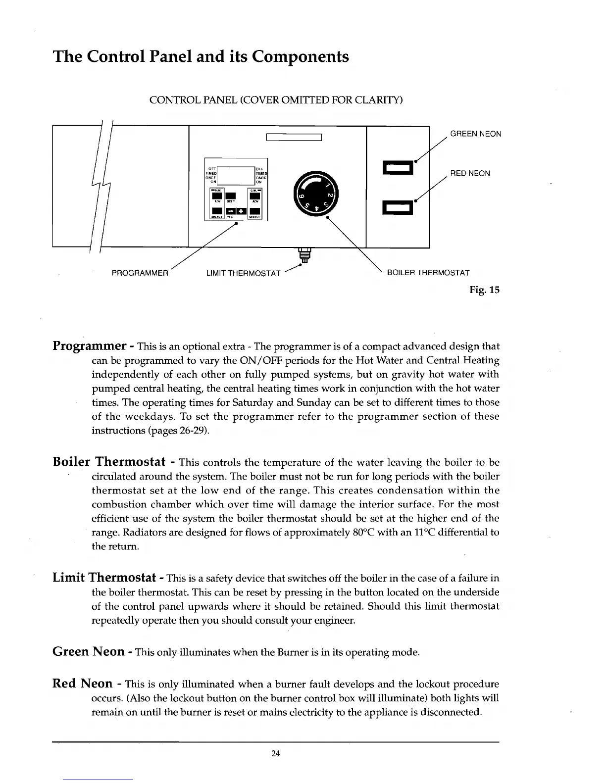
CONTROL PANEL (COVER OMITTED FOR CLARITY)
I I
OF~
10FF
g~~~~~~~
ON,-,
__
--''ON
ii.
1iI,-
AnI/
SET'
.....
I I
.aD.
SElECT
YES
GREEN NEON
RED NEON
PROGRAMMER LIMIT THERMOSTAT /
BOILER THERMOSTAT
Fig. 15
Programmer
- This is
an
optional extra - The
programmer
is of a compact
advanced
design
that
can be
programmed
to
vary
the
ON/OFF
periods
for the
Hot
Water
and
Central
Heating
independently
of
each
other
on
fully
pumped
systems,
but
on
gravity
hot
water
with
pumped
central heating, the central heating times
work
in
conjunction
with
the
hot
water
times. The operating times for
Saturday
and
Sunday
can be set to different times to those
of
the
weekdays.
To
set
the
programmer
refer
to
the
programmer
section
of
these
instructions (pages 26-29).
Boiler
Thermostat
- This
controls
the
temperature
of
the
water
leaving
the
boiler
to
be
circu.lated
around
the system. The boiler
must
not
be
run
for-
long
periods
with
the boiler
thermostat
set
at
the
low
end
of
the
range.
This
creates
condensation
within
the
combustion
chamber
which
over
time
will
damage
the
interior
surface.
For
the
most
efficient
use
of
the
system
the
boiler
thermostat
should
be
set
at
the
higher
end
of
the
range. Radiators are designed for flows of approximately 80°C
with
an
11
°C differential to
the return.
Limit
Thermostat
- This is a safety device
that
switches off the boiler
in
the case of a failure
in
the boiler thermostat. This
can
be reset
by
pressing
in
the
button
located
on
the
underside
of
the
control
panel
upwards
where
it
should
be
retained.
Should
this limit
thermostat
repeatedly operate
then
you
should
consult
your
engineer.
Green
Neon
- This only illuminates
when
the Burner is
in
its
operating
mode.
Red
Neon
- This is only illuminated
when
a
burner
fault develops
and
the
lockout procedure
occurs. (Also the lockout
button
on
the
burner
control box will illuminate)
both
lights will
remain
on
until
the
burner
is reset
or
mains electricity to the appliance is disconnected.
24