Two Pipe System
Where
it
is
not
possible to install a gravity oil
supply
system
then
a
two
pipe
pumped
system
must
be
installed. The oil
in
this
arrangement
is
drawn
from the
tank
by
the
pump
on
the burner,
and any
excess is
returned
via
the
second
pipe
to
the
tank
If a
two
pipe
system
is to
be
fitted,
the
pump
on
the
burner
will require to
be
modified from
that
supplied
(See Burner Manual).
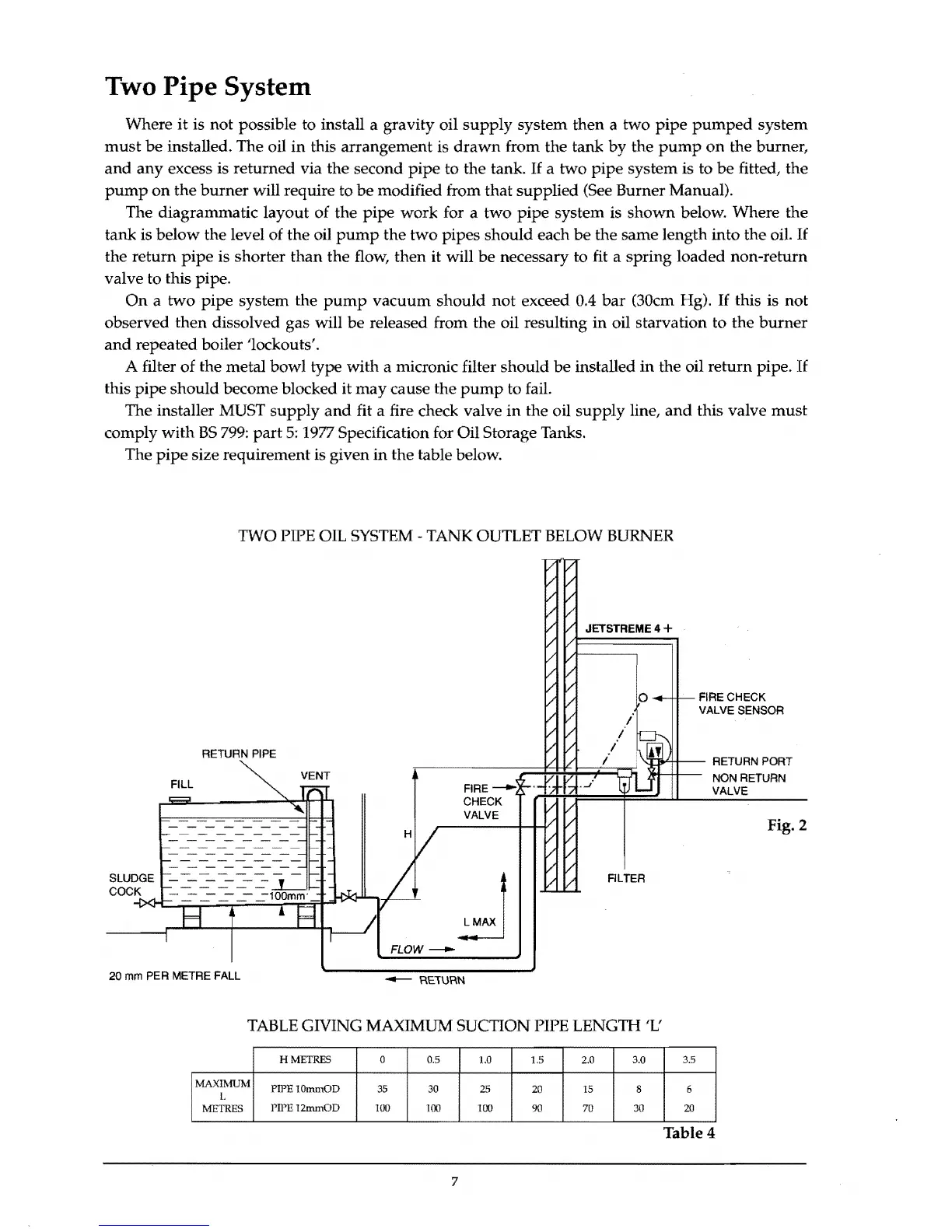
The
diagrammatic
layout
of
the
pipe
work
for a
two
pipe
system is
shown
below. Where
the
tank is
below
the level of
the
oil
pump
the
two
pipes
should
each
be
the
same
length
into
the
oil. If
the
return
pipe
is shorter
than
the
flow,
then
it will
be
necessary to fit a
spring
loaded
non-return
valve to this pipe.
On
a
two
pipe
system
the
pump
vacuum
should
not
exceed 0.4
bar
(30cm Hg). If this is
not
observed
then
dissolved gas will
be
released from
the
oil resulting
in
oil starvation
to
the
burner
and
repeated boiler 'lockouts'.
A filter
of
the
metal
bowl
type
with
a micronic filter
should
be
installed
in
the oil
return
pipe. If
this
pipe
should
become blocked it
may
cause
the
pump
to fail.
The installer MUST
supply
and
fit a fire check valve
in
the
oil
supply
line,
and
this valve
must
comply
with
BS
799:
part
5:
1977 Specification for Oil Storage Tanks.
The
pipe
size requirement is given
in
the
table below.
TWO PIPE OIL SYSTEM - TANK OUTLET BELOW BURNER
JETSTREME
4 +
FIRE
CHECK
VALVE
SENSOR
VENT
.-------------;;::::~~F=F::r::F1
'.::t:J[j.Lf-jf-----
RETURN
PORT
A
NON
RETURN
RETURN
PIPE
FILL
SLUDGE
COC~K~~~~~~~~~~~~L-~
FL
OW ----Il1o-
FILTER
VALVE
Fig. 2
20
mm
PER
METRE
FALL
--
RE1\.lRN
TABLE GIVING MAXIMUM SUCTION PIPE LENGTH
'L'
HMETRES 0
0.5 1.0 1.5 2.0
3.0 3.5
MAXIMUM
L
PIPEI0mmOD
35
30
25
20 15 8 6
METRES
PIPE
12mmOD
100 100 100
90
70
30 20
Table 4
7