This document provides installation and maintenance instructions for the Bentone B 30 A2.2H oil burner, designed to provide sustainable energy solutions. It covers general information, technical specifications, electrical equipment, installation procedures, pump details, service guidelines, and fault location.
Function Description
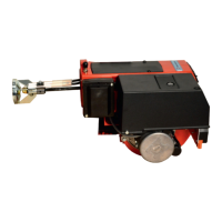
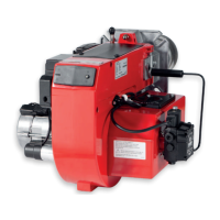
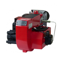
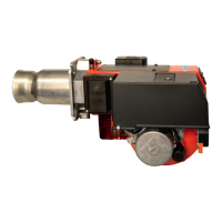
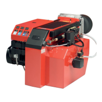
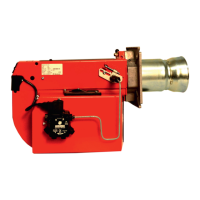
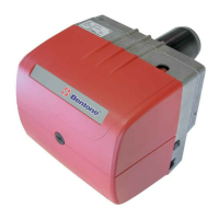
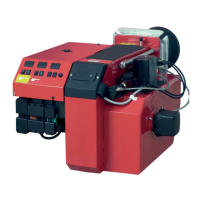
The Bentone B 30 A2.2H is an oil burner intended for operation in installations according to EN 303 and EN 267. When used with a hot air boiler, it requires the LMO24.255 or LMO44.255 control unit. The burner is designed to provide sustainable energy solutions by efficiently burning fuel oil.
The core of the burner's operation involves a safety system that ensures safe startup and continuous operation. This system includes safety switches for hatches, doors, water level, pressure, and temperature, all installed in accordance with current regulations. The wiring diagram illustrates the electrical connections, including the oil burner control (A1), flame detector (B1), fuse (F1), various lamps (H1, H2, H3), motor (M1), operating switches (S1, S2), control thermostats (S3, S6), temperature limiter (S4), micro switch for hinged door (S5), main switch (S7), ignition transformer (T1), and solenoid valves (Y1, Y2, Y2H).
The LMO14/24 control unit manages the burner's sequence of operations. Upon activation of the operating switch and twin thermostat, a spark is generated, the air damper motor opens to the low load position, and the burner motor starts. A prepurge period follows, after which solenoid valve 1 opens. Oil mist is formed and ignited, detected by the photocell, which then extinguishes the ignition spark. The control unit monitors for flame establishment within a safety time limit; failure to do so results in a lockout. If the flame disappears during operation, the burner attempts to restart. The burner can operate at full or low load, controlled by the high/low thermostat. In case of a lockout, a red lamp on the control unit illuminates, and pressing the reset button restarts the burner. Fault codes, indicated by flashes of the reset button's red light, provide diagnostic information for issues such as no flame signal, false light during start, losses of flame, preheater time-out, or wiring faults.
The oil distribution system is crucial for reliable operation. The SUNTEC A2L oil pump, a key component, features two nozzle outlets and two independent blocking solenoid valves, with a single regulator for both nozzle lines. It draws oil from the tank through a built-in filter, pressurizes it, and delivers it to the nozzle lines via the cut-off solenoid valves. In two-pipe operation, a by-pass plug ensures bypassed oil returns to the tank, and bleeding is automatic. In one-pipe operation, the by-pass plug is removed, and the return is plugged, with bypassed oil returning directly to the gear inlet. The solenoid valves are "normally closed" and ensure fast, independent switching for precise control of oil flow to the nozzles.
Important Technical Specifications
- Model: B 30 A2.2H
- Control Unit: LMO24.255C2E, A2L 65 CK
- Fuels: HVO/XTL (EN 15940), Fuel oil (DIN 51603-1), Fuel oil A Bio 10 (DIN 51603-6)
- Burner Output: 55-175 kW (4.5-15.0 kg/h)
- Main Supply: 230V, 1~, 2.6/3.1A, 50Hz, IP20
- Max Fuse Rating: 8A
- Preheater Current (excluded): Elmin 1.30A (281W), Elmax 1.40A (297W)
- NOx-class: 4
- NOx (GCV) preheater excluded: 119mg/kWh
- Noise Level: 82dBA (can be reduced with silencer or air duct connection)
- Ambient Temperature (Operation): -10 to +60 °C (max. 80% relative humidity, no condensation)
- Surface Temperature: May exceed 60 °C
- Ignition Electrodes Setting: a: 3.5-4.0, b: 7.0-9.0, c: 2.0-3.0, d: 5.0-6.0
- Nozzle Types: 45°, 60°, 80° Solid/semisolid
- Pump Pressure: 10 bar (8-25 bar depending on pump model)
- SUNTEC A2L 65CK/75CK Pump:
- Viscosity Range: 2-12 mm²/s
- Pressure Range: 8-15 bar
- Rated Voltage of Coil: 220/240V, 50/60 Hz
- Oil Temperature: max 60°C
- LMO14.113... / LMO24.255... Control Unit Data:
- Preignition Time: 15 s / 25 s
- Prepurge Time: 16 s / 26 s
- Postignition Time: 3 s / 5 s
- Safety Lockout Time: < 10 s / < 5 s
- Reset Time after Lockout: < 1 s / < 1 s
- Reaction Time on Flame Failure: < 1 s / < 1 s
- Ambient Temperature: -5 - +60°C / -20 - +60°C
- Min Detector Current (with flame): 45 μA dc
- Max Perm. Detector Current (without flame): 5.5 μA dc
- Maximum Permitted Vibration Level: 5.0 mm/s
Usage Features
The burner is designed for ease of installation and adjustment, though all work must be performed by authorized personnel. Basic settings are provided to facilitate initial startup and flame establishment, but fine-tuning is required to adapt to the specific installation and fuel type. This includes adjusting air settings for low and high load positions, which can be read on the damper scale. The nozzle table assists in selecting appropriate nozzles based on desired output and pump pressure.
The control unit's color codes and fault codes offer clear indicators for operational status and troubleshooting. Solid yellow indicates preheater in operation, flashing yellow for ignition, solid green for normal operation, and flashing green for poor flame signal. Red lights indicate faults, with specific flash sequences corresponding to different issues, such as no flame signal, false light, flame losses, or preheater time-out.
The oil pump's design allows for both one-pipe and two-pipe oil distribution systems, providing flexibility depending on the installation requirements. Bleeding in two-pipe operation is automatic, simplifying maintenance.
Maintenance Features
Regular inspection and maintenance are crucial for the burner's longevity and efficient operation. A service schedule is provided, recommending annual or 3,000-hour intervals for various components.
Service Schedule Highlights:
- Burner: 1 year / 3,000 h
- Filter: 1 year replacement / 3,000 h replacement
- Oil Hose: 1 year inspection/replacement
- Nozzle: 1 year replacement / 3,000 h replacement
- Electrodes: Replacement/cleaning 1 year / 3,000 h replacement
- Brake Disc: Replacement/cleaning 1 year / 3,000 h replacement
- Motor: 1 year / 3,000 h
- Drive Shaft: Check/replace in event of damage
- Fan Wheel: Replace if need for cleaning/imbalance
- Oil Filter: Once a year / 3,000 h replacement
- Oil Valve: Tightness check once a year / Replace if leakage detected
Component Replacement Intervals:
- Control System: 10 years / 250,000 cycles
- Pressure Switch: 10 years / 250,000 cycles
- Ignition System with Flame Guard: 10 years / 250,000 cycles
- UV Flame Sensor: 10,000 h / N/A
- Damper Motor: 500,000 cycles
- Contactor: 10 years / 500,000 cycles
Key Maintenance Procedures:
- Delivery Inspection: Verify all goods are delivered and undamaged.
- Start-up: Conduct flue gas analysis and temperature measurement for correct setting, ensuring chimney temperature is at least 60 °C.
- Oil Line Seals: Check for leaks after installation and operation, retightening coupling elements as needed.
- Pump Filter Replacement: Disconnect power and fuel, loosen pump cover screws, replace filter and gasket, then refit and restart.
- Solenoid Valve Replacement: Disconnect power and fuel, disconnect electrical cables, loosen nut and screws, remove and replace valve, then refit and check operation.
- Gasket Seal Replacement (Pump): Disconnect hoses and cables, loosen pump screws and locking rings, remove old seal, install new seal, then reconnect and test.
- Combustion Device Maintenance: Loosen fan housing, remove brake plate and electrode holder for cleaning/replacement, replace nozzle (do not clean soiled nozzles), check ignition electrodes, clean flame tube, then refit and check combustion.
- Air Damper Maintenance: Note settings, loosen screws, remove intake grille, clean air damper and intake, lubricate shaft, then refit and check combustion.
- Fan Maintenance: Disconnect power, loosen motor screws, check fan wheel for damage/skew, clean/replace fan wheel, then refit and check operation.
- Drive Shaft Replacement: Disconnect power, loosen motor screws, remove drive shaft and coupling, replace coupling, then refit and check operation.
- Oil Pump Replacement: Disconnect hoses and cables, loosen screws, pull out pump, fit new coupling, then refit, bleed, set pressure, and check combustion.
- Electrical Component Replacement: Disconnect power, note connections, fit new component, then switch on and check operation.
- Vibration Check: Monitor vibration levels (max 5.0 mm/s), check fastener tightness, fan wheel for damage/contamination, and motor shaft/bearings for wear.
Important Safety Notes:
- All installation and maintenance work must be carried out by trained and authorized personnel.
- Always disconnect power and shut off fuel supply before working on electrical or fuel line components.
- Handle with caution; the burner has moving parts and surfaces can exceed 60 °C.
- Use hearing protection when the burner is in operation, as noise levels can exceed 85 dBA.
- Ensure proper air supply and fire safety measures are in place.
- Only use Bentone original parts for replacements.
- After servicing components affecting combustion, perform flue gas analysis and soot test.
- Do not put the burner into operation without proper safety and protection devices.