Do you have a question about the Bentone B30 and is the answer not in the manual?
Technical drawings and dimensions for B30 and B40 models.
Operating range chart for B30 model, showing kg/h and kW.
Operating range chart for B40 model, showing kg/h and kW.
Guidance on selecting nozzles and pump pressure based on boiler conditions.
Specifies settings for ignition electrodes and brake plate for B30/B40.
Comprehensive table of nozzle capacities, kW, and Mcal/h for various pump pressures.
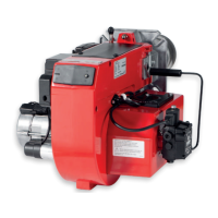
Identification and labeling of burner components with numbered diagrams.
Guidelines for safe handling and lifting of the burner unit.
Procedures for checking delivered goods for damage and correctness.
Steps to take before installing the burner, checking compatibility and specifications.
Recommendations for designing the oil distribution system for reliable operation.
Instructions for safe and compliant electrical hookup of the burner.
Directs users to technical data for selecting the appropriate nozzle.
Basic settings for brake plate and air flow, requiring post-adjustment checks.
Guidance on ensuring the boiler flange hole pattern matches the burner flange.
Step-by-step procedure for physically installing the burner onto the boiler.
Procedure for checking and tightening oil line connections for leaks.
Formulae and guidance for calculating the necessary prepurge time based on boiler type and output.
Table providing recommended excess air levels for light oil based on flue gas analysis.
Example settings for a B40 burner to achieve a 200 kW output.
Graph showing recommended settings for the nozzle assembly on B 30 models.
Graph showing recommended settings for the air damper on B 30 models.
Graph showing recommended settings for the nozzle assembly on B 40 models.
Graph showing recommended settings for the air damper on B 40 models.
How to adjust the nozzle assembly for optimal pressure drop and combustion.
Procedure for adjusting the air damper for correct air flow.
Guide to setting the air pressure switch for proper burner safety and operation.
Detailed steps for removing and installing components of the combustion assembly for servicing.
Instructions for servicing the air damper, including cleaning and lubrication.
Steps for safely removing and replacing the oil pump unit.
Procedure for replacing electrical components, including noting connections.
Checks related to vibration, including bolts, nuts, and motor bearings.
Technical data and component identification for the Suntec AS47CK pump.
Explanation of the operational principles of the Suntec AS47CK pump.
Tables providing guidance on suction pipe length based on height and line diameter.
Electrical wiring diagram for the LAL 2.25 control system.
List of electrical components used in the LAL 2.25 system with their designations.
Description of the operational features and safety functions of the LAL control system.
Detailed breakdown of the burner's startup sequence and timing.
Explanation of fault types, lockout indicators, and reset procedures.
Troubleshooting guide for symptoms and causes when the burner fails to start.
Troubleshooting guide for issues arising after the burner has been in normal operation.
Troubleshooting guide for delayed ignition and pulsating burner operation.
Troubleshooting guide specifically for delayed ignition issues.
Troubleshooting guide for diagnosing and resolving noise issues in the pump.
Troubleshooting guide for issues related to the pump's inability to build pressure.
Key checks to perform before starting the burner for operation.
Steps to take if the burner fails to initiate operation.
Troubleshooting steps when the burner ignites but fails to produce a flame.
Critical safety warnings regarding burner startup and ignition.