Do you have a question about the Bentone BG 400 and is the answer not in the manual?
Crucial safety guidelines for burner operation, installation, and handling.
Emergency procedures to follow in case of gas leaks to ensure safety.
Recommended intervals for routine maintenance and servicing of the burner.
Guidelines for timely replacement of burner components based on usage.
Procedures to verify the burner and its components upon delivery.
Detailed physical dimensions and measurements of the BG 400 burner.
Specifications on the burner's power output (kW) and gas flow rates.
Information on permitted gas types and their categories for use.
Graphical representation of operational limits and parameters for the burner.
Electrical requirements, safety standards, and specifications for the burner.
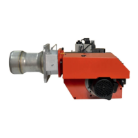
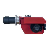
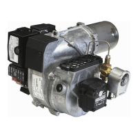
Identification and overview of the burner's main components with a diagram.
General principles and regulations for installing and maintaining the burner.
Guidance for the user on burner operation and installation.
Recommended frequency and procedures for inspection and maintenance.
Steps required to safely initiate the burner's operation after installation.
Steps for verifying and optimizing the burner's performance post-installation.
Verifying delivered items and checking for transit damage.
Ensuring burner compatibility with the boiler and checking specifications.
Guidelines for correct installation of the gas supply system.
Instructions for safely connecting the burner to the electrical supply.
Initial adjustments for the brake plate and airflow before service.
Steps for physically attaching the burner to the boiler unit.
Checks before initial operation, including gas nozzle, quality, de-aerating, and electric tests.
Diagrams and dimensions for different gas nozzles (Propane, Natural gas, Biogas).
Steps to adjust the air supply for optimal combustion using flue gas analysis.
How to adjust the brake plate to control airflow.
Instructions for inspecting and adjusting the burner head components.
How to adjust the air pressure switch to ensure proper combustion air supply.
Adjusting the gas pressure switch to prevent operation with low gas pressure.
A schematic diagram of the CPI components and their connections.
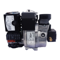
General introduction and identification of the Multi-Bloc components.
Instructions for installing the CPI on the valve.
Procedure for adjusting the governor to control gas pressure.
Steps for setting the start gas flow rate using valve V3.
How to adjust the main gas flow rate using valve V2.
Schematic diagrams illustrating the Multi-Bloc's gas flow and electrical connections.
Guidelines for optimal excess air levels based on gas type.
Methods for calculating the required gas quantity for the system.
A practical example demonstrating how to calculate gas quantity.
Detailed steps for removing, servicing, and reinstalling the combustion assembly.
Procedures for maintenance and cleaning of the air dampers.
How to check and monitor the flame and ionisation current for proper operation.
Guidelines for installing safety systems in accordance with regulations.
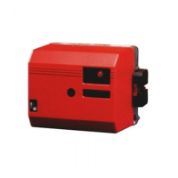
Electrical schematic illustrating the wiring connections for the LME control system.
Explanation of the burner's operational sequence and functions.
How the control program indicates disruptions and fault codes.
Standards and regulations for installing gas burners correctly.
Routine maintenance tasks and cleaning instructions for the boiler room.
Steps to take and checks to perform when the burner has stopped.
Procedures for safely switching off the burner and gas supply.
Important safety precautions to observe during operation and inspection.