This document provides a comprehensive guide for the BG 400-2 gas burner, covering its description, technical data, installation, operation, and troubleshooting.
Device Description
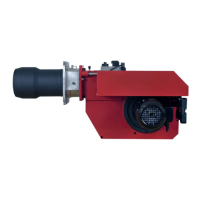
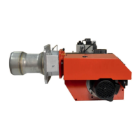
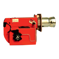
The BG 400-2 is a fan gas burner designed for various applications. It features a robust construction with clearly identifiable components for easy maintenance and adjustment.
Components
The burner consists of several key components:
- Switches (0-I, I-II): For controlling the burner's operating stages.
- Cover, inspection glass: Allows visual inspection of the flame.
- Reset button: For restarting the burner after a lockout.
- Air pressure switch: Monitors fan pressure.
- Damper motor: Controls the air damper for air volume adjustment.
- Inner assembly adjustment: For fine-tuning the burner's internal components (not for town gas).
- Flame cone: Directs the flame into the combustion chamber.
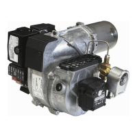
- Multibloc: An integrated unit containing several gas control components.
- Connecting pipe: Connects various parts of the gas train.
- Air damper: Regulates the amount of combustion air.
- Air intake: Where combustion air enters the burner.
- Gas pressure switch: Monitors gas pressure.
- Ball valve: For isolating the gas supply.
- Electrical panel: Houses electrical connections and controls.
- Fan wheel: Generates the airflow for combustion.
- Electrical connection: For power supply.
- Motor: Drives the fan wheel.
- Ignition electrode: Initiates the ignition spark.
- Transformer: Provides high voltage for the ignition electrode.
- Ionization electrode: Detects the presence of a flame.
- Inner assembly: The core combustion components.
- Nozzle: Delivers gas into the combustion chamber.
- Brake plate: Part of the combustion head, adjustable for pressure drop.
Technical Specifications
Dimensions
The BG 400-2 has a standard length of 172 mm for the burner tube, with a measure A of 155 mm. A long design is available with a burner tube length of 272 mm and measure A of 255 mm. The town gas version has the same dimensions as the standard design. The overall dimensions are maximum measurements and may vary depending on the components used. The flange dimensions include an M10 bolt pattern, an outer diameter ranging from 175-240 mm, and an inner diameter of 140 mm.
Output Range
The burner is available in a 400 kW capacity model.
- Capacity: 60-318 kW (Natural gas/LPG).
- Gas volume at minimum output: Natural gas 6 Nm³/h, LPG 2.3 Nm³/h (5.0 kg/h).
- Gas volume at maximum output: Natural gas 31.8 Nm³/h, LPG 12.2 Nm³/h (24.8 kg/h).
- Max. Inlet pressure: 100 mbar.
- Rated inlet pressures: Natural gas 20 mbar, LPG 20 mbar.
- Gas fittings: Natural gas/LPG 1".
- Motor: 1-phase, 0.25 kW, 2800 r/m, 230 V.
- Ignition transformer: Primary 230 V, 1A; Secondary 8000 V.
Calorific values:
- Natural gas: 10 kWh/Nm³
- LPG: 26 kWh/Nm³
The capacity chart, according to EN 676, shows the relationship between pressure (mbar) and power (kW), indicating the operational envelope of the burner.
Usage Features
Mounting on the Boiler
Installation involves removing the combustion unit, fitting the flange and gasket to the boiler, and drilling new fixing holes if necessary. The valve unit and fan house unit can be removed for easier access during installation and service. Gas connection is made via the ball valve, ensuring easy removal for inspection.
Skeleton Diagrams (2-Stage or Modulating Burners)
The wiring diagram illustrates the electrical connections for the gas burner control (LMG22.../LGB22...). Key components include the gas burner control, ionization electrode, operating fuse, lamps, alarm signal, burner motor, damper motor, time meters, operating switches, control thermostats, temperature limiter, micro switch for hinged door, main switch, air pressure switch, ignition transformer, and various plug-in contacts and solenoid valves.
Function (2-Stage Design)
The burner operates in a sequence:
- Start-up: Operating switch ON, thermostat ON, gas pressure switch ON, air damper closed. The burner motor starts after verifying no fan pressure.
- Air damper motor opens: The damper opens to full load, and the air pressure switch confirms sufficient fan pressure.
- Air damper motor closes: The damper closes to low load, and the ignition spark is formed.
- Main and safety valves open: Gas is ignited, and the ionization electrode detects a flame.
- Safety time expires: The ignition spark extinguishes. If no flame is detected or if it disappears, the burner control locks out.
- Operating position: The burner operates, alternating between full and low load based on temperature settings.
- Stop: Operation can be interrupted by the operating switch or thermostat.
Lockout: Indicated by a red lamp. Restart by pressing the reset button.
Control Diagnosis
The control system provides lockout indications and error codes via the red fault LED. After a lockout, the LED is steady on. Pressing the reset button for >3 seconds initiates a blink code sequence, allowing diagnosis of the fault cause. Error codes correspond to specific issues such as no flame establishment, faulty electrodes, gas valve issues, air pressure monitor faults, extraneous light, or internal device faults.
Measures and Checks Before Start-up
Before starting the burner, several checks are crucial:
- Inner assembly: Ensure ignition and ionization electrodes are correctly adjusted.
- Gas quality: Verify the burner head is compatible with the gas quality.
- Venting: Vent the gas line by loosening the screw on the test nipple.
- Leakage control: Check for leaks in the gas supply system with solenoid valve closed, using a pressure gauge and soapy water.
- Electric function test: Verify correct phase and neutral, closed gas shut-off cock, and proper pre-purging and pre-ignition periods. For 2-stage and modulating burners, observe damper movement during pre-purging.
Determination of Gas Volume
The document provides an example for calculating gas volume (Nm³/h) based on boiler output (kW), calorific value (kJ/Nm³ or kWh/Nm³), and expected efficiency. It also includes a formula to adjust for deviations in barometer height, pressure, and temperature of the gas.
Adjustment of Multi-Bloc (MB-ZRDLE 405-420)
The Multi-Bloc is a key component with several adjustable features:
- Max. inlet pressure: 360 mbar.
- Adjustable governor pressure: Ranges from 4-50 mbar depending on the model.
- Solenoid valve: Slow opening valves with adjustable start load for stage 1 and stage 2.
Adjustments:
- Flow adjustment (2-stage design): Loosen lock screw 'a'. Turn hydraulic device 'e' for stage 1 and 'b' for stage 2 to increase or reduce gas flow.
- Adjustment of governor: Adjust outlet pressure using a screwdriver. Turning right increases pressure, turning left reduces it.
- Adjustment of start gas flow: Remove protective cover 'c'. Turn adjustment knob 'd' to set desired start gas flow. Turning right reduces flow, turning left increases it.
Air Adjustment (2-Stage Design)
The damper motor controls the air damper between three positions: fully closed, low load, and full load, using colored cams.
- Changing air volume: Remove the damper motor cover and turn the cams.
- Low load adjustment: Adjust the orange cam (0° for reduced air, 90° for increased air).
- Full load adjustment: Adjust the red cam (0° for reduced air, 90° for increased air). If the red cam is moved, adjust the black cam accordingly.
- Releasing button: Allows easy rotation of the damper for motor exchange.
Maintenance Features
General Instructions
- Adjustment of burner: Fine-tune the burner to the specific boiler, checking flue gas temperatures, water temperature, and CO₂/O₂ concentration.
- Commissioning: Control combustion quality using a flue gas analysis device, aiming for approximately 20% excess air.
- Service: Only qualified personnel should perform service. Replacement parts must be original or approved. Re-commissioning is required if the burner is converted for a different gas quality.
- Inspection and maintenance: Daily inspection is advisable.
- Adjustment of burner head: Adjust the brake plate position to achieve the correct pressure drop for pulsation-free combustion.
Flame Monitoring and Measurement of Ionisation Current
- Ionisation current: Check on start-up and during service calls. A low current can indicate leaks, bad earth connection, dirt, faulty flame electrode position, or a poor gas/air mixture.
- Measurement: Use a microampere meter connected in series with the flame electrode and gas burner control. Minimum required current varies by gas control type (e.g., LMG 2 μA, LGB 10 μA).
Gas Pressure Switches
- Min. gas pressure switch: Prevents burner start-up if gas pressure is too low and stops the burner during operation if pressure drops. Adjustment involves setting the desired switch-off pressure using the knob.
- Max. gas pressure switch (optional): Stops the burner if gas pressure exceeds a set value, requiring manual restart.
Air Pressure Switch
- Function: Stops the burner if air volume is reduced. It should operate before supervised pressure falls below 80% of the controlled stage and before CO content exceeds 1% by volume.
- Adjustment range: 1-10 mbar (LGW 10) or 2.5-50 mbar (LGW 50).
Fault Location Guide
The guide provides a systematic approach to troubleshooting common burner issues:
- Burner does not start: Check gas cocks, fuses, thermostats, electrical connections, motor, and gas relay.
- Burner motor running but no ignition: Check voltage, ignition electrodes, and transformer.
- No flame establishment: Check gas solenoid valve, voltage, air pressure switch, and starting load.
- Burner locks out after safety time: Check ionization current, UV-cell, and gas relay supervision.
- Burner locks out during pre-purge: Check air pressure switch, starting load, and gas pressure.
- Pulsations at start/during operation: Check ignition electrodes, gas pressure, flue gas side, burner adjustment, cleanliness, and chimney.
- Burner operating correctly but locking out now and then: Check ionization current, UV-cell, voltage drop, air pressure switch, and spark-over in ignition electrodes.
- Bad combustion: Check ambient temperature of gas relay, ignition spark, chimney, boiler load, leaks, draught, excess air, air shortage, nozzle, fresh air intake, and burner head position.
- Condensation in boiler and chimney: Check flow gas temperature and gas supply, insulate chimney.
Handing Over of the Installation
After installation, ensure repeated start attempts are successful, gas switch operates at set value, burner locks out when air pressure switch hose is removed, protective covers are mounted, and test reports are filled. Instruct users on operation and maintenance. Inspection and service must be performed by authorized personnel. A fault location guide is provided for common issues, emphasizing checking electricity, gas, and air supply.