Do you have a question about the Bentone BF1 RME and is the answer not in the manual?
Rules for using the burner with FAME fuel and general installation guidelines.
Manual content must be observed by all personnel working on the unit.
Electrical installation must follow regulations to avoid risks of fire or personal injury.
Details burner output and basic settings for Model BF1 FUV 63-16.
Details burner output and basic settings for Model BF1 KV 76-26.
Provides physical dimensions of the BF1 burner.
Details the dimensions of the different flanges for the BF1 burner.
Recommends nozzles and pressures based on boiler types and furnace loads.
A table listing nozzle capacities and corresponding kW output for pump pressures between 8-15 bar.
Notes adjustments for oil quantity reduction when using a preheater.
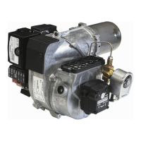
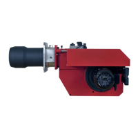
Lists and identifies the various components of the BF1 burner with numerical labels.
Lists and identifies the various components of the BF1 burner with numerical labels.
Ensures all delivered goods are present and free from transport damage.
Checks burner suitability and capacity range for the specific boiler.
Guidance on correctly laying out the oil supply system for reliable operation.
Instructions for safe electrical connection, requiring power to be switched off.
Refers to technical data for selecting the appropriate nozzle.
Details basic burner setting procedures, including flue gas analysis.
Covers the steps for physically installing the burner onto the boiler.
Checks if the burner's hole pattern matches the supplied flange.
Step-by-step guide for installing the burner, including flange, front piece, and electrodes.
Instructions for connecting oil pipes, including filter installation and purging.
Details how to connect the plug (X4) according to the wiring diagram.
Provides an example of basic setting for specific burner models.
Explains how to choose the correct nozzle based on burner output and pump pressure.
Lists the air setting and insert setting values for a 30 kW burner.
Adjusts brake plate position for correct pressure drop and good combustion.
Adjusts combustion airflow using the air regulator for optimal combustion.
Explains how turning the screw affects airflow based on air intake position.
Discusses inlet cone position affecting airflow, usually left in standard position.
Allows rotation of the air intake to adapt the burner to different surroundings.
Describes the available dimensions for the hose connection air duct.
General warnings for authorized personnel performing service work.
Describes different service positions for accessing burner components.
Step-by-step guide for placing the burner in service position 1.
Step-by-step guide for placing the burner in service position 2.
Step-by-step guide for placing the burner in service position 3.
Details visual inspection and maintenance of the combustion assembly.
Procedure for replacing the preheater, including steps before and after.
Step-by-step instructions for replacing the oil pump and associated components.
Procedure for removing and installing the fan motor and related parts.
Instructions for servicing the air intake and inlet cone components.
Describes how to inspect the fan wheel for dirt or damage.
Details performing a visual inspection of the fan wheel.
Provides a method for cleaning the fan wheel and fan housing.
Offers a second alternative method for cleaning the fan wheel and fan housing.
Checks the electrical console retaining screw for proper earth contact.
Procedure for replacing the entire electrical package of the burner.
Instructions for replacing individual electrical components like the oil burner control.
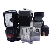
Details regarding the Suntec ANV47C pump.
Provides technical specifications for the Suntec ANV47C pump.
Lists and identifies the components of the Suntec ANV47C pump.
Procedure for replacing the filter in the pump.
Instructions for converting the pump system to a one-pipe configuration.
Instructions for converting the pump system to a two-pipe configuration.
Details about the solenoid valve used with the pump.
Explains the working principle of the Suntec ANV47C pump and its solenoid valve.
Tables for calculating suction pipe length based on height and diameter.
Suction pipe tables for overhead tanks with one-pipe and two-pipe systems.
Suction pipe tables for underlying tanks, recommending a Tigerloop.
Explains the function of the FPHE 5 preheater and its thermostat.
Diagram illustrating the electrical connections for the LMO1..2..4.. control system.
Lists and identifies electrical components used in the control system.
Describes the operational sequences and functions of the LM01..2..4.. control system.
Provides technical data for the LM014 and LM024 control units.
Explains the meaning of signal lights and color codes for burner status.
Lists fault codes indicated by flashing lights and their meanings.
Troubleshooting guide for when the burner fails to start, listing causes and remedies.
Troubleshooting steps for issues occurring after the burner has been running.
Diagnoses and provides remedies for delayed ignition, starting issues, and pulsation.
General advice on keeping the boiler room clean and ensuring proper ventilation.
Checks to perform before starting the burner, like oil tank level and pipe valves.
Steps to take if the burner fails to start, including checking reset buttons and thermostats.
Guidance for when the burner starts but fails to ignite the flame.
Instructions for proper shutdown procedures during summer or extended periods.
Safety warnings regarding burner start-up, naked flames, and unburnt gases.