Do you have a question about the Bentone BF1 Series and is the answer not in the manual?
Key safety guidelines for installation and operation to prevent hazards.
Critical warnings to read before installation, operation, and maintenance for safe use.
Guidelines for electrical safety, assembly, and servicing to ensure correct installation.
Information on managing flue condensation, increasing temperature, and adjusting the burner.
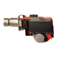
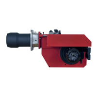
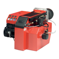
Specifications for the overall dimensions of the BF1 burner unit.
Detailed measurements and specifications for different flange types used with the burner.
Technical details specific to the BF1-2 K 76-26 model, including output.
Charts and data relating burner output to basic operational settings and parameters.
Table detailing recommended nozzles and operating pressures for various output levels.
Information regarding the use of a preheater and its impact on oil quantity.
Manufacturer's declaration of product conformity with relevant standards and EC directives.
Steps for verifying delivery and preparing the site for burner installation.
Instructions for correctly setting up the oil supply system and making electrical connections.
Guidance on selecting the nozzle and initial airflow adjustments before burner operation.
Detailed steps for physically installing the burner onto the boiler, including pipe connections.
Ensuring the correct hole pattern matches the flange for secure burner mounting.
Specific instructions for connecting oil pipes and completing electrical wiring for operation.
An illustrative example of basic settings for two-stage burners, covering output and settings.
Recommended settings for nozzle selection and air intake for optimal burner performance.
Procedure for adjusting the nozzle assembly to achieve good combustion without pulsation.
Steps for adjusting the air damper and control plate for optimal air flow at different loads.
Information on the inlet cone's role in airflow and its standard position for operation.
How to rotate the air intake for different installation environments and its effect on airflow.
Description of the available air duct sizes and how to install them on the air intake.
General warnings for servicing and specific positions for accessing burner components.
Detailed steps for placing the burner into Service Position 1 for maintenance.
Detailed steps for placing the burner into Service Position 2 for maintenance.
Detailed steps for placing the burner into Service Position 3 for maintenance.
Procedure for inspecting and servicing the burner's combustion assembly, including nozzle and electrodes.
Step-by-step guide for replacing the preheater unit on the burner.
Instructions for safely removing and installing a new oil pump on the burner.
Detailed procedure for replacing the burner's fan motor unit.
Procedures for servicing the air intake system and inspecting the fan wheel.
Steps for visually inspecting the fan wheel for dirt or damage.
Method for cleaning the fan wheel and housing using a specific procedure.
Alternative method for cleaning the fan wheel and housing, involving motor removal.
Checks and maintenance for the electrical module and its connections.
Procedures for replacing the complete electrical package or individual electrical components.
Guide for replacing the damper motor on the burner assembly.
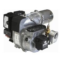
Introduction to the Suntec AT2 45C pump, including technical data and components.
Explanation of how the Suntec AT2 45C pump operates in one- and two-pipe systems.
Tables detailing suction pipe lengths for different line diameters and tank configurations.
Specific suction pipe length guidelines for overhead tank installations.
Specific suction pipe length guidelines for underlying tank installations.
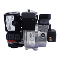
Introduction to the Danfoss BFP 52E pump, including technical data and components.
Explanation of the operational principles of the Danfoss BFP 52E pump.
Tables for suction pipe lengths for the Danfoss BFP 52E pump.
Instructions on how to purge the pump system for one-pipe configurations.
Description of the FPHB 5 preheater's function and operation.
Details on the FPHB 5-LE preheater, including its LE-valve functionality.
Schematic diagram illustrating the electrical wiring for a 2-stage burner control.
A list of electrical components used with the LMO/LMO/LOA burner controls.
Explanation of how the LMO/LMO/LOA burner controls operate during different stages.
Technical specifications and parameters for the LMO/LMO/LOA burner control units.
Common causes and remedies for the burner not starting, including symptom analysis.
Troubleshooting steps for when the burner fails to start after a period of normal operation.
Identifying and resolving problems related to delayed ignition, pulsation, and hot flue gases.
Guidelines for boiler room cleanliness, safety during maintenance, and proper shutdown.
Procedures for addressing issues when the burner starts but fails to ignite properly.
Instructions for summer shutdown and critical warnings related to burner start-up.
| Burner Type | Pressure jet |
|---|---|
| Fuel Type | Light Oil |
| Control System | Electronic |
| Air Supply | Forced draft fan |
| Ignition | High voltage |