28
Bentone BF1
General
H
H
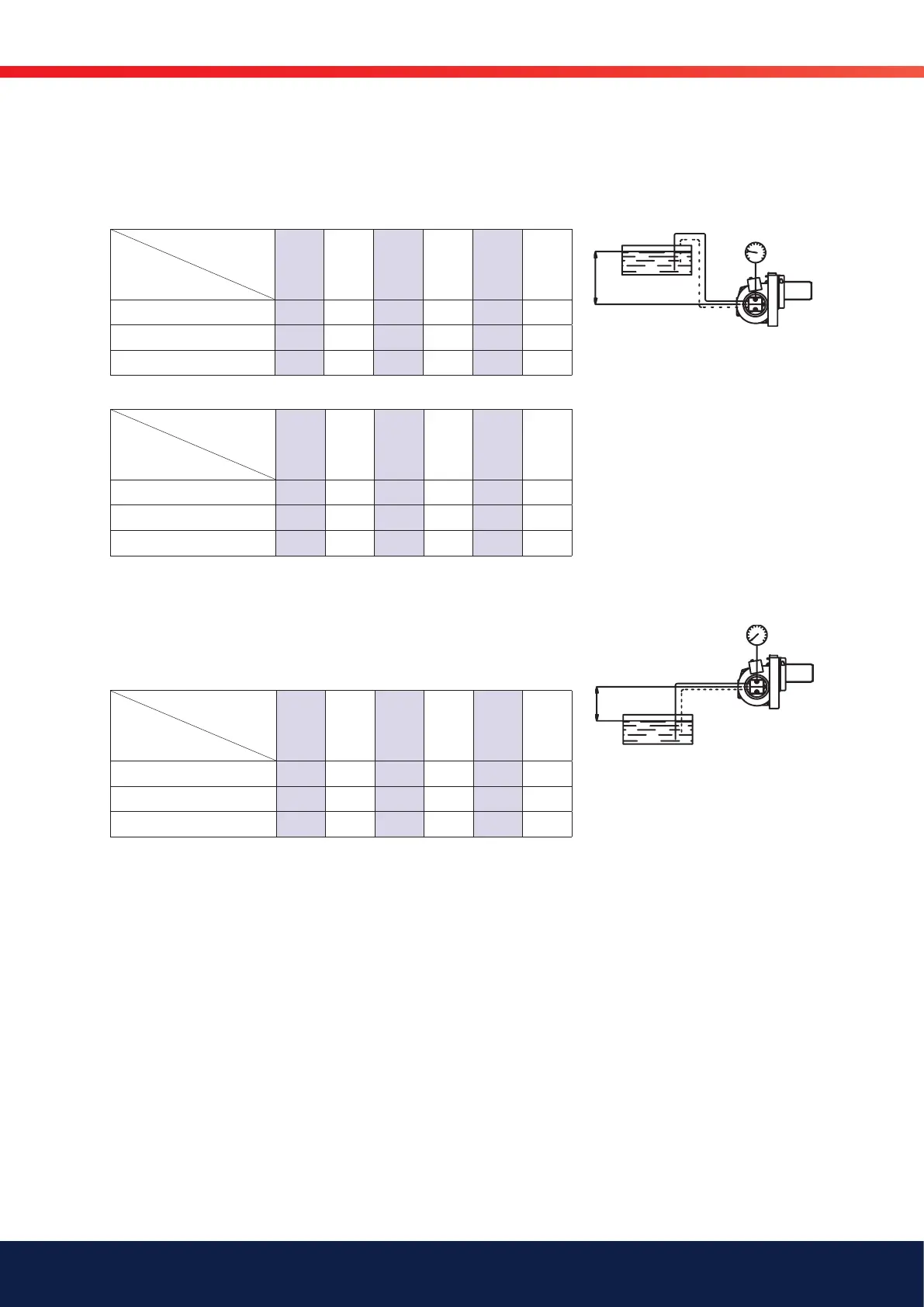
5.1.4 Suction pipe tables AT2 45C
5.1.4.1 Overhead Tank
One-pipe system
Height m
Line diameters
4,0 3,0 2,0 1,0 0,5 0,0
ø 4 mm 28 24 21 18 16 14
ø 6 mm 100 100 100 92 83 75
ø 8 mm 100 100 100 100 100 100
Two-pipe system
Height m
Line diameters
4,0 3,0 2,0 1,0 0,5 0,0
ø 6 mm 29 25 22 18 16 14
ø 8 mm 96 85 73 61 55 49
ø 10 mm 100 100 100 100 100 100
5.1.4.2 Underlying Tank
One-pipe system
For reliable operations, use of a Tigerloop is recommended in underlying
tanks.
Two-pipe system
Height m
Line diameters
0,0 -0,5 -1,0 -2,0 -3,0 -4,0
ø 6 mm 14 12 10 7 3 0
ø 8 mm 49 43 37 26 14 2
ø 10 mm 100 100 94 65 37 8
The suction line tables consist of theoretically calculated values where the
pipe dimensions and oil velocity have been matched so that turbulences will
not occur. Such turbulences will result in increased pressure losses and in
acoustic noise in the pipe system. In addition to drawn copper piping a pipe
system usually comprises 4 elbows, a non-return valve, a cut-off valve and
an external oil filter.
The sum of these individual resistances is so insignificant that they can be
disregarded. The tables do not include any lengths exceeding 100 m as
experience shows that longer lengths are not needed.
The tables apply to a standard fuel oil of normal commercial quality according to
current standards. On commissioning with an empty tube system the oil pump
should not be run without oil for more than 5 min. (a condition is that the pump is
being lubricated during operation).
The tables state the total suction line length in metres at a nozzle capacity of
3,0 Gph. Max. permissible pressure at the suction and pressure side is 2,0
bar. For two-pipe system Q
max
= 55l/h pump capacity at 0 bar.