ELECTRIC EQUIPMENT
GAS BURNER CONTROL: LMG22.../LGB22...
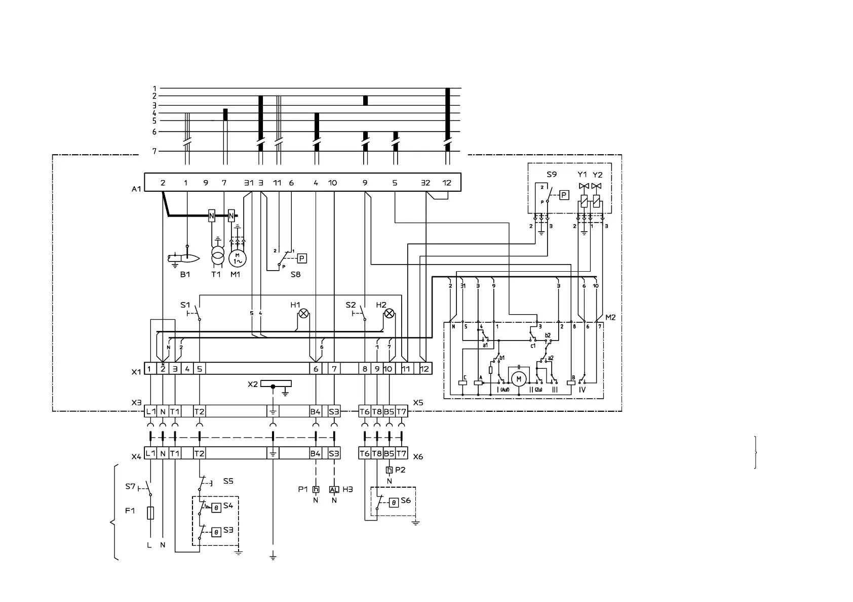
WIRING DIAGRAM
COMPONENT LIST
A1 Gas burner control
B1 Ionization electrode
F1 Operating fuse
H1 Lamp, low capacity
H2 Lamp, high capacity
H3 Alarm signal 230 V
M1 Burner motor
M2 Damper motor, L&S SQN75.254.A21B
P1 Time meter, total operating time
P2 Time meter, high capacity, total opera-
ting time
S1 Operating switch
S2 Operating switch, stage 2
S3 Control thermostat
S4 Temperature limiter
S5 Micro switch for hinged door
S6 Control thermostat, stage 2
S7 Main switch
S8 Air pressure switch
T1 Ignition transformer
X1 Connection terminal board
X2 Earth terminal
X3 Plug-in contact, burner
X4 Plug-in contact, boiler
X5 Plug-in contact, stage 2, burner
X6 Plug-in contact, stage 2, boiler
S9 Gas pressure switch
Y1 Gas solenoid valve 1 MultiBloc
Y2 Gas solenoid valve 2
Mains connection in accordance with local
regulations.
172 425 28 02-01
If there is no
Plug-in con-
tact (X4,X6) on
the boiler, con-
nect to the
contact enclo-
sed.
If S6 is missing connect T6 and T8.
 Loading...