Copyright © BEP Marine Limited, All rights reserved
INST-600-GD-V5
29/11/07
Page 6
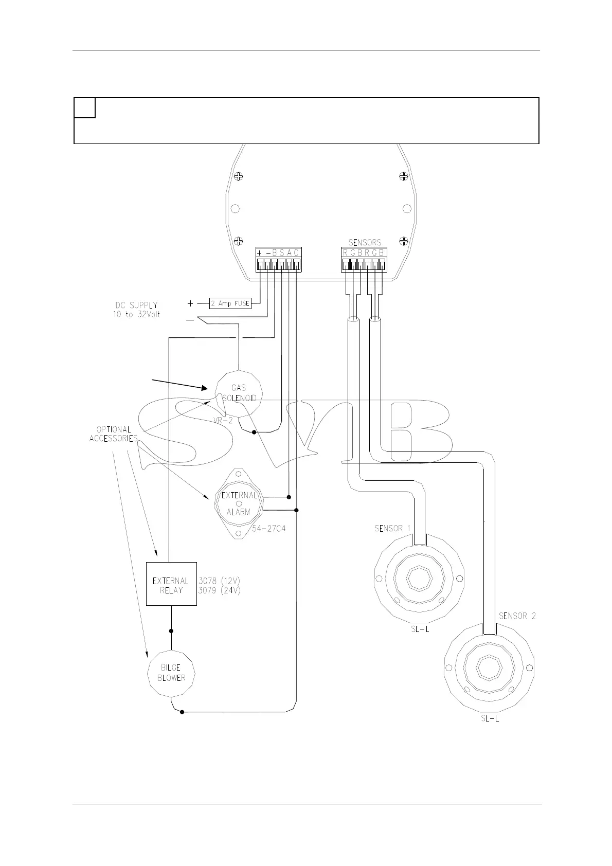
9 Wiring Diagram
10 Control Head Installation
For ease of operation, the control head should be mounted in a convenient position close to your gas
appliances and in a position where the control head can be seen and heard easily. The unit can be
either surface mounted or recessed into a 2.5mm panel.
Important Note:
If using one sensor, A link
wire must be wired
between B and G on the
unused sensor side
1
GDL ONLY