11
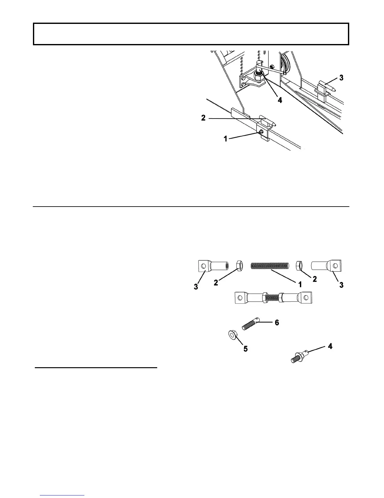
Prepare the adjusting link as shown.
Apply some grease on the adjusting rod (item 1).
Insert the two nuts (item 2) on the adjusting rod and
screw to the middle.
Install the two links (item 3) on each end of the adjusting
rod.
NOTE: In some cases it may be necessary to cut the
adjusting rod (item 1).
Insert a flange nut (item 5) (head first) on the bolt (item
6) and screw down to the end of the threads as shown
(item 4).
For the Cub Cadet 2000 and 2500 series: Items 4,5
and 6 are not required.
You will be using the 5/16’’ x 1 1/4’’ hex bolt and 5/16’’
nut and a 3/8’’ x 1’’ hex bolt and nut.
ASSEMBLY
Prepare the pins
Prepare the adjusting link
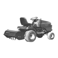
NOTE: If the tractor is equipped with a transmission
that has a distance between the bolts of 14",
interchange the mounting pins (item 2 on the left
side and item 3 on the right side) to get a distance of
12 1/4’’ center to center between the pins.
Loosen the square head set screw (item 1) that holds
the mounting pins (right and left) (items 2 & 3).
Slide the mounting pins towards the back of the frame.
Unscrew and remove the hitch pin (item 4).