Replacing the control PCB
Open the control housing under the green chamber by unscrewing the two Phillips
screws on the front just 2/3 of the way. Now carefully pull the front cover away by
grasping the two screws.
When putting the front cover back on again later on, make sure that the seal in the
control housing is correctly positioned. Before finally tightening the two Phillips
screws again, please press the front cover at the four corners with your finger tips. In
this way, you can make sure that the front cover seals properly onto the housing again.
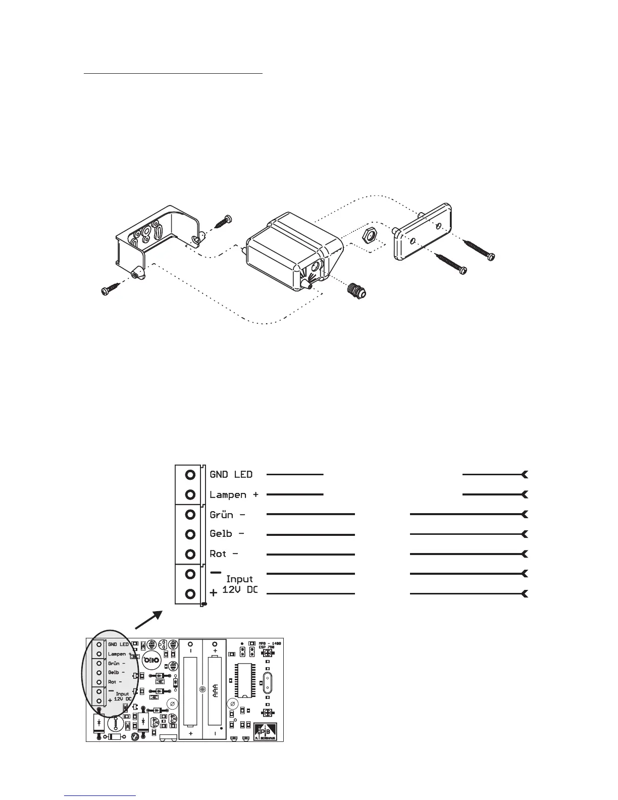
To replace the control PCB, please separate from the operating voltage by
disconnecting the batteries in the battery casing. Now disconnect the cable lead from
the control PCB to the signal head by simply pulling the plug terminal upwards. This
means that you do not have to unscrew the cables. Please pay attention to correct
polarity when fitting the new control PCB.
Colour of the wire/wires
Explosion drawing of
MPB 1400 control housing parts.
11
violet + grey + grey/pink
black + white + pink
green
yellow
red
blue
brown
The control PCB is fitted with buffer
batteries (cannot be recharged) which
maintain the program when changing the
main battery.
For your own safety, replace these buffer
batteries every twelve months, using top
quality alkali micro batteriesAAA.
(GND LED)
(Lamps +)
(Green –)
(Yellow –)
(Red –)
(– Input
+ 12V DC)