9
5.2 Installing cable glands
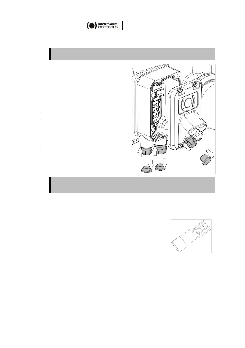
How to install cable glands
For each cable entry used
1. Remove plug from the cable
entry (M20 entry for control
or M25 entry for power) with
the adjustable wrench.
2. Separate sealing nut from
its cable gland.
3. Screw and tighten cable
gland in the cable entry.
4. Thread the sealing nut on
the cable and pass the cable
through the cable gland.
Unused entries must be kept closed by their plugs as they are part
of the components allowing actuator IP68 protection setting.
5.3 Wiring power and control
Crimping the wires
Terminal plate is fitted with tab terminals,
compatible with 6.35mm crimp receptacle lugs
with insulated funnel.
These lugs allow wire section between 1.5 and
2.5mm².
Once cables are installed in the cable glands, crimp end of
every wire to be connected with a lug.
Procedure is the same for connection compartment and connector.