EasyManua.ls Logo

Bernard EZ Series User Manual

Bernard EZ Series
64 pages
To Next Page IconTo Next Page
Page #1 background imageLoading...
Page #1 background image
INSTRUCTIONS DE MISE EN SERVICE,
STOCKAGE ET ENTRETIEN
INSTRUCTIONS FOR START-UP,
STORAGE AND MAINTENANCE
ANLEITUNG FÜR DIE INBETRIEBNAHME,
LAGERUNG UND WARTUNG
NR 1208_EZ_revH_A/F/D
Art: 5100134
EZ
Gamme
Range
Question and Answer IconNeed help?

Do you have a question about the Bernard EZ Series and is the answer not in the manual?

Bernard EZ Series Specifications

General IconGeneral
BrandBernard
ModelEZ Series
CategoryController
LanguageEnglish

Summary

1 SAFETY INFORMATION

2 ASSEMBLY

3 HANDWHEEL OPERATION AND DECLUTCHING

EZ4, EZ100-1000, EZ60 Models

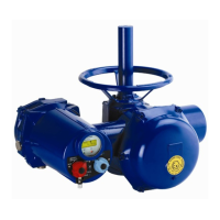
Manual declutching methods for EZ4-EZ15, EZ100-1000, and EZ60 actuator models.

4 COMMISSIONING FOR SWITCH ACTUATOR

4.1 ELECTRICAL CONNECTIONS AND PRELIMINARY TESTS

Checking electrical connections and performing initial tests.

4.2 SETTING OF MECHANICAL STOPS AND TRAVEL LIMIT SWITCHES

Adjusting mechanical stops and travel limit switches.

4.1 ELECTRICAL CONNECTIONS AND PRELIMINARY TESTS

Setting Travel Limit Switches

Setting travel limit switches using cams on the actuator.

4.3 POSITION FEEDBACK POTENTIOMETER

Potentiometer Adjustment

Adjusting potentiometer resistance for signal feedback on support columns.

4.4 «TAM» POSITION TRANSMITTER

TAM Transmitter Configuration

Signal direction inversion and settings for the TAM transmitter.

4.5 AUXILIAIRY CONTROL SWITCHES

4.6 HEATING RESISTOR

4.7 CAUTION

5 COMMISSIONING OF EZ LOGIC ACTUATOR

5.1 PRODUCT DESCRIPTION

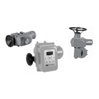
Description of EZ LOGIC control versions and features.

5.1.1 Keyboard

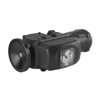
Description of the actuator's local control keypad and functions.

Local command Inhibition

Explanation of local command inhibition and unlocking.

5.1.1 Keyboard

Power and Control Board Connections

Details on the power board and control board connections.

5.2 WIRING

5.2.1 Opening of actuator

Procedure for opening the actuator cover and connecting the ribbon cable.

5.2.1 Opening of actuator

Power Supply Connection Details

Power supply connection details for different voltage types.

5.2.2 Power supply

5.2.3 Remote command

Voltage Command Details

Details on voltage command types and connections.

INPUT POSITION SIGNAL FOR POSITIONNER

POSITION FEEDBACK

0-10VDC Position Signal

Obtaining 0-10VDC position signal by adding a resistor.

5.2.4 Opened/Closed signaling

5.2.5 Alarm signaling

5.3 FAST COMMISSIONING

Fast Commissioning Procedure

Detailed steps for setting valve positions and mechanical stops.

5.4 CONFIGURATION BY SWITCHES

5.4.1 Motor direction of rotation

Setting the motor rotation direction for opening and closing.

5.4.2 Remote position signal (EZxxxx KL XX 123 A0 only)

Configuring remote position signals (0/20mA, 0/10VDC).

5.4.3 Selection of ON-OFF operation (EZxxxx KL XX 123 A0 only)

Selecting between proportional and ON/OFF operation modes.

5.5 CONFIGURATION BY PROGRAMMING

5.5.1 Flowchart

Overview of the main menu entries for configuration.

5.5.1 Flowchart

Entering Configuration Menus

Entering the main and sub-menus for configuration.

5.5.3 Description of 'set configuration' menu

5.5.4 Description of 'read configuration' menu (rd CFG)

5.5.5 Read the existing alarm codes (rd Err)

5.6 TROUBLE SHOOTING

Local Mode and Remote Command Issues

Troubleshooting local mode entry and remote command problems.

Operation and Direction Issues

Diagnosing no operation, wrong direction, or blinking light issues.

Analog Input Signal Issues

Troubleshooting 0-20mA, 0-10V, and 4-20mA analog input signal problems.

Display and Keypad Issues

Feedback and Signaling Issues

Alarm Code Interpretation

6 TORQUE LIMITER

7 MAINTENANCE AND STORAGE INSTRUCTIONS

Maintenance

Routine checks and recommendations for actuator maintenance.

Storage

Instructions for storing actuators in a warehouse or before connection.

Storage of Electronic Components & Post-Storage Checks

Discouraging long-term storage and outlining post-storage procedures.

CABLAGE SERVOMOTEUR - EZ4 à EZ15 monophasé

Legend/Legend

Explanation of symbols used in the wiring diagram.

CABLAGE SERVOMOTEUR - EZ25 à EZ60 monophasé

Légende/Legend

Explanation of symbols used in the wiring diagram.

CABLAGE SERVOMOTEUR - Autres modèles EZ

Servomoteur / Actuator Component Wiring

Detailed component connections for various actuator types.

Motor Wiring Types

Wiring diagrams for three-phase, single-phase, and DC motors.

CABLAGE SERVOMOTEUR - Autres modèles EZ

3 PHASES / DREI PHASEN

Wiring diagram for 3-phase power supply connection.

1 PHASE / EINE PHASE

Wiring diagram for single-phase power supply connection.

CABLAGE SERVOMOTEUR - Autres modèles EZ

Control Panel Sample Designs

Sample control panel designs and wiring examples.

SCHEMA DE CABLAGE - EZ logic

POSITIONNER OPTION

Options for position transmitter and signal connections.

USER CONNECTION

Client connection details for power supply and control.

CABLAGE SERVOMOTEUR - EZ6-EZ15 courant continu precable

Versions sans limiteurs d'effort / Without torque limit switches versions

Wiring for versions without torque limit switches.

BC GROUP

Agents and Distributors List

List of global agents and distributors for Bernard Controls.

Bernard Controls Main Contact

Bernard Controls main contact and address information.

Related product manuals