33
- Measuring voltage: 0.25 V.
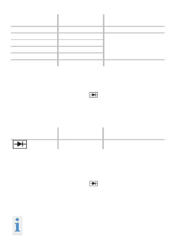
Diode test
With the selector switch set to " / ◦))". Insert the black test
lead into the ‘COM’ socket and the red test lead into the
V/Ω/TEMP/CAP socket. Using the test probes, touch the test
points of the test object. Red test lead = anode, black test
lead = cathode. The forward voltage drop is displayed.
- Forward current: approx. 25 µA, reverse voltage: approx.
2.8 V.
Continuity testing
With the selector switch set to " / ◦))". Insert the black test
lead into the ‘COM’ socket and the red test lead into the
V/Ω/TEMP/CAP socket. Using the test probes, touch the test
points of the test circuit. An acoustic signal is emitted if a re-
sistance under 70 Ω is measured.
Important: Isolate from the power supply and dis-
charge capacitors in the circuit to be measured.
 Loading...