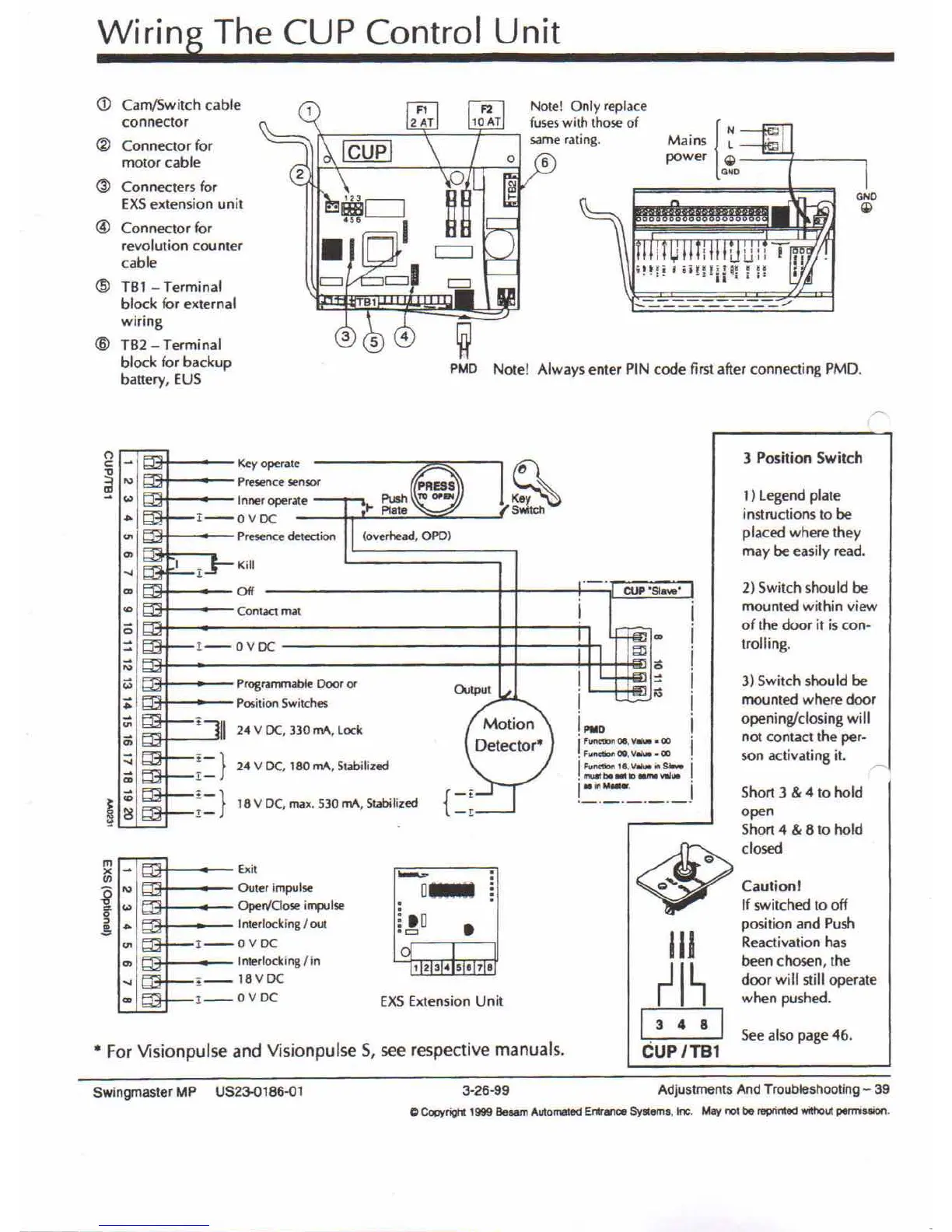
Wiring The CUP Control Unit
. {N
Mains L
power Ql
000
- ---- -=- -=-----
-=-
-=---.,./
Note! Only replace
fuses with those of
same rating.
PMO Note! Always enter PIN code first after connecting PMD.
(j)
Cam/Switch cable
connector
@
Connector for
motor cable
(ID
Con necters for
EXSextension unit
@
Connector for
revolution counter
cable
@
TBl - Terminal
block for external
wiring
@
TB2 - Terminal
block for backup
battery, EUS
• For Visionpulse and Visionpulse 5, see respective manuals.
3 Position Switch
1) legend plate
instructions to be
placed where they
may be easily read.
2) Switch should be
mounted within view
of the door it is con-
trolling.
3) Switch shou Id be
mounted where door
openingfclosing will
not contact the per-
son activating
it.
r
See also page 4&.
IIJ
rl~
13
4 8
I
CUP/TBl
Short 3 & 4 to hold
open
Short 4 & 8 to hold
<$>
c10sed
Q
Q'"
Caution!
If switched to off
position and Push
Reactivation has
been chosen, the
door will still operate
when pushed.
CUP
"S1a ••••"
i
i
i
i
= 1
1
;;l
i
!
PlIO
i
I
Functioll 08.
Viii"" • OJ
I'
• F",nctiotI OQ,
VIII ••• 00
I
FlIftC'lion 1e,
V.u. ill
s •••••
I'
• f'IlU*tbll •• lOaIM ••••••
!.:.~::~~._._j
~
Switch
12345078
•.•....
D_
o
i
10
0=
1
EXS Extension Unit
(overhead. OPO)
Kill
Key operate
Presence senSOf
Inner operate
I--OVDC
Presence detection
Off
I
Contact mat
Exit
Outer impulse
OperVCioseimpulse
Interlocking
I
out
I--OVDC
Interlocking I in
, __ 18VDC
!__
OVDC
1--0VDC
Programmable Door
0(
Position Switches
i
II
24 V DC, 330 mA, Lock
~=}
24 V DC. 180 rnA, Stabilized
~::} 18 V DC, max. 530 rnA, Stabilized
(")
c:
..,
~
'"
'"
<-
'"
0>
...
'"
.,
<;;
=
~
'"
<Z
:;:
'"
0;
::;
c;
i
iC
~
m
~
x
en
i
'"
'"
••
<-
-='
'"
0>
...
'"
Swingmaster MP US23-0186-Ql
3-26-99
Adjustments And Troubleshooting - 39
o
Copyrigl1: 1999
Besam
Automa1ed Entrance
Syllems,
toe.
May
not
be reprinted
withOut
pemission.