20
KEY SWITCH TERMINATIONS
{
The standard panel key switch can be used to tap off
a switched positive ignition feed to power additional
gauges. In this way these gauges will only be live whilst
the engine is running, the engine is starting or the heaters
are being used.
For silver key switches, the terminal to achieve this
ignition switched positive is marked ‘AC’.
For panels with push buttons, gauges can be driven
from the 1mm
2
brown wire which terminates at 11 way
connector terminal 4. This is a lower power switched
positive, any additional power required from this
connection must be feed through a relay.
NB: Key switch terminals are rated at 10 amps
maximum, since they are already utilised for panel and
alternator feeds Beta Marine recommend any additional
requirements from these terminals must be fed through
a relay. This relay should then be connected to it’s own
fused positive supply directly from the engine battery.
Please refer to diagram index on page 52 for an
illustration of a typical electric fuel lift pump with ignition
switched, relay.
All Beta Marine engines are supplied as standard with 12
volt electric starting. 24 volt electric starting is available as
an optional extra at placement of order.
CONTROL PANELS
Beta Marine offer 10 control panel options, standard for
heat exchange is the ABV panel, standard for keel cooled
is the AB or C panel. For further information please refer
to pages 24, 25, 46, 47 & 48.
1. Control Panels must be fitted in a location where the
helmsman can either see or hear the alarm system.
2. Control panels are supplied as standard with a 3m
multi-core cable for connection to the engine wiring
loom. Extension looms of 5m or more are available
should your installation require it or you wish to
relocate your existing panel/s, all looms include a start
relay to overcome the voltage drop.
3. For standard wiring diagrams see diagram index, page
52.
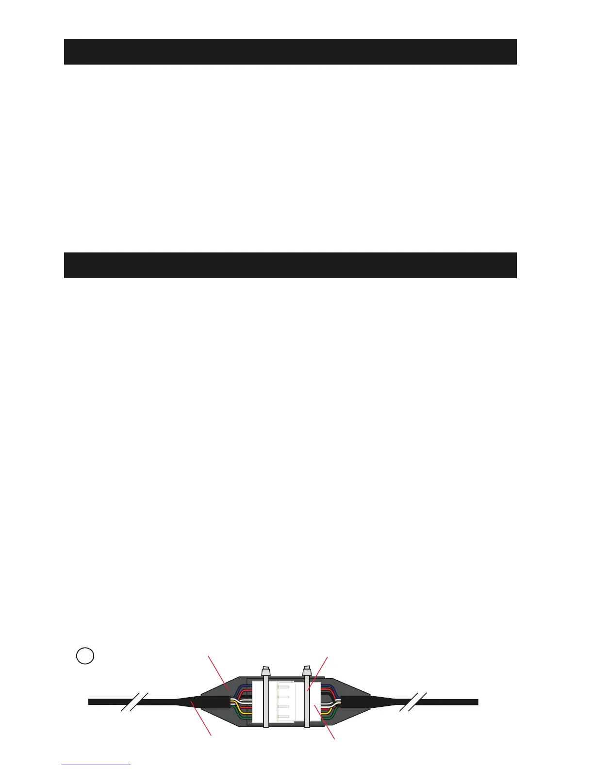
4. All electrical equipment must be protected from sea
water. Sea water or rust in the starter motor will
invalidate the warranty. Care must be taken when
pushing the two halves of the interconnection plugs
together to ensure that individual pins do not fall
out. To prevent corrosion and assist in assembly we
recommend that the plug is packed with petroleum
jelly (Vaseline) and then carefully pushed together. The
plastic boots should cover both halves and overlap.
A cable tie is then put around to hold the two halves
in position and help prevent any ingression of water.
See illustration below.
5. The control panels must not be installed where rain
and or sea water/spray can reach them. If vulnerable,
we recommend that a suitable flap or cover is fitted.
6. All cables must be adequately clipped and protected
from abrasion.
7. Electrical systems shall be designed and installed so as
to ensure proper operation of the craft under normal
conditions of use and shall be such as to minimise risk
of fire and electric shock.
8. Attention shall be paid to the provision of overload
and short circuit protection of all circuits, except engine
starting circuits, supplied from batteries.
9. Ventilation must be provided to prevent the
accumulation of gases, which might be emitted
from batteries. Which should be firmly secured and
protected from any possible ingress of water.
CONTROL PANEL INSTALLATION
{
Engine
Cable Tie
 Loading...