D-Cell Battery Powered Version:
Size Height Width* Depth**
Inches 5.6 8.4 4.8
Centimeters 14.2 21.3 12.2
*Width includes feet
**Depth with SnapHead pump cartridge in place.
Weight
115VAC/230VAC version: 1.85 lbs/0.84 kg
D-Cell Battery Powered version: 1.57 lbs/0.72 kg*
*D-Cell Battery Powered version without batteries
COMPONENTS
Enclosure
Molded ABS plastic, water-resistant, flame-resistant
Pump
Peristaltic, self-priming and self-checking,
6 Volts DC
Speed & Displacement
Battery-Powered Units: 5.5 oz per min (153 ml per min)*
Line-Powered Units: 7.5 oz per min (222 ml per min)*
*With Silicone tubing. Results may vary depending on voltage,
chemical viscosity, temperature and other factors. Always
perform your own test with your unit to confirm actual pump
speed.
Maximum Duty Cycle
At temperatures up to 85°F/29°C: 4 hours of pump down-time
required for every 20 minutes of continuous run.
At temperatures over 85°F/29°C: 12 hours down-time for every
20 minutes of continuous run time.
Hydraulic Performance
Maximum Vacuum: 8 in of mercury
Maximum Pressure: 20 psi
Tubing Material
Silicone
Viton
Coin Battery
3 Volt Lithium BR2032 or CR2032
Regulatory
CSA CE
DR-2000/115 VAC U.S.
DR-2000/230 VAC E.U.
DR-2000/6V
For confirmation of regulatory compliance, see rating label on
your DR-2000.
INSTALLATION
Refer installation and service to qualified
personnel only.
Installation must comply with all applicable
plumbing and electrical codes.
MOUNTING
The DR-2000 should be mounted so the LCD screen can be
viewed easily. It should be located close enough to both the
injection point and liquid supply to ensure unobstructed
delivery.
1. Align the metal mounting bracket and mount on a smooth
surface using screws.
2. Place the DR-2000 over the mounting bracket and slide it
down tight.
3. If desired, a screw can be placed in one of the feet to hold
the unit in place.
The DR-2000 can also be mounted using the
three plastic feet. If mounting on an uneven
surface, be careful not to over-tighten or snap
the feet off.
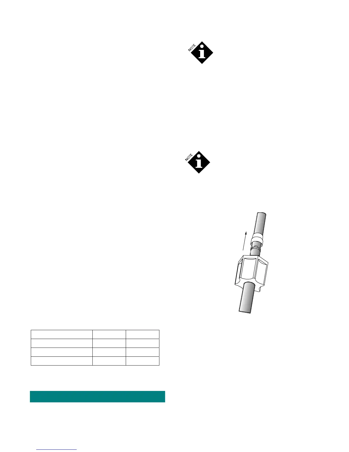
INSTALLING SUPPLY LINES
1. Cut the desired length of 1/4-inch (6mm) chemical feed
line and attach it to the nut of the left side (suction side) of
the pump squeeze tube.
D
R
2
0
0
0
M
F
0
3
Figure 3. Installing the Chemical Feed Line to the
Squeeze Tube Fitting.
2. For the chemical uptake side, a standpipe is provided. Cut
the bottom of the chemical feed line tubing at a 45-degree
angle and press it into the standpipe. Insert the chemical
feed line 0.5 inches (12 mm) above the bottom of the
standpipe. Both the 45-degree cut and the 0.5 inch (12 mm)
distance above the bottom of the standpipe will help avoid
the formation of a seal with the bottom of the chemical
drum and ensure an unobstructed chemical uptake.
2 1210730 DR-2000 (R14735-00, Rev C) February 2010
 Loading...