Transport, installation and connection
4-9
A
B
technology for your future
Automation
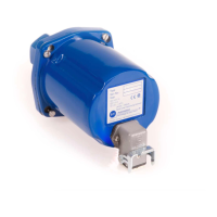
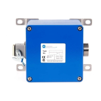
BFI
Type
Ser.-No.:
24Vdc
Germany
B
F
I
T
y
p
e
S
e
r
.
-
N
o
.
:
2
4
V
d
c
G
e
r
m
a
n
y
4.6.2 Adapting the flame scanner to the fuel
Danger to life caused by combustion or explosion !
In case of incorrect installation or adjustment, un-
controlled combustion or explosions may be caused
!
Observe the adjustment instructions of the plant op-
erator !
Adjustment work may be carried out only by quali-
fied and approved specialist staff !
All alignments and settings have to be carried out,
when new spare parts have been fitted, the flame
scanner has been moved or the flame image has
been changed (by additional fuel, new burner,
change in the burner / air register, for example) as
well as during all first installations.
For selective burner amplifiering, the device has to
be installed in such a way that the primary combus-
tion zone in all load ranges is inside the visual angle
of the flame scanner. The sight axle has to cut
through the first third of the flame (A) of the own
burner if possible. The extension of the sight axle
must not cut through the first third of the flame of
other burners.
 Loading...