Transport, Installation and Connection
4-11
4.8.2 Terminal diagram
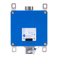
Connection of compact flame controller
Internal External
Contact
Conductor
colour Function
Burner
control
mA
display Power supply
1 wh Flame relay lead x
2 br Flame relay Flame ON x
3 pk Flame relay Flame OFF x
4 gn Power supply +24V DC +24V DC/200mA
5 ye Power supply GND - GND
6 gr Analog output + (0/4 to 20 mA) +
7 bl
Switchover to channel 2
(+24V DC ext.) (x)
8 rd Fault output +24 VDC/100 mA (x)
Connection of compact flame controller with internal heating (optional)
Internal External
Contact
Conductor
colour Function
Burner
control
mA
display Power supply
1 - 6 as for standard controller
7 bl Power supply to heater (+) +24V DC / 500mA
8 rd Power supply to heater (-) GND