• With the help of an adequate support, lift the motorised head until the
track is levelled, as in fig.11.
• Fix the two supporting brackets to the ceiling, as in fig.12. Recheck
everything and fix the two supporting brackets to the gearmotor base
plate.
• Release the towing carriage (fig.13) by pulling the wire, and bring the
towing arm as far as the door panel. Fix the towing arm to the door panel,
as in fig.14, using the screws supplied.
5) ELECTRICAL INSTALLATION SET-UP (Fig.15)
I) Type-approved omnipolar circuit breaker with at least 3-mm contact
opening, provided with protection against overloads and short circuits,
suitable for cutting out automation from the mains. Place, if not al
ready installed, a type-approved differential switch with a 0.03 A
threshold just before the automation system.
Qr) Control panel and incorporated receiver
M) Actuator
Ft) Transmitter photocell
Fr) Receiver photocells
T) 1-2-4 channel transmitter.
Connect the accessories, safety and control devices to the motor unit,
making sure that the mains voltage connections are kept totally separate
from the low voltage accessory connections. Proceed as illustrated in the
electrical diagram.
5.1) Terminal board connections (Fig.16)
WARNINGS - For wiring and installation operations, refer to the
current standards and good technical principles.
Wires powered at different voltages must be physically separated, or
suitably insulated with at least 1 mm extra insulation. The wires must be
clamped by an extra fastener near the terminals, for example by bands.
WARNING! For connection to the mains, use a multipolar cable with
a minimum of 3x1.5mm
2
cross section and complying with the
previously mentioned regulations. For example, if the cable is out side
(in the open), it has to be at least equal to H07RN-F, but if it is on the
inside (or outside but placed in a plastic cable cannel) it has to be or
at least egual to H05VV-F with section 3x1.5mm
2
.
JP1
1 Transformer input 0 V
2 Transformer input 15 V
3 Transformer input 24 V
JP14 (only available in the SCE-MA S boards)
4 TX1 serial output
5 TX2 serial output
6 RX1 serial input
7 RX2 serial input
JP5
8-9 not used
10-11 START button input (N.O.).
10-12 STOP button input (N.C.). If not used, leave the jumper connected.
10-13 Photocell input (N.C.).
10-14 Fault input (N.O.). Input for photocells provided with N.O. checking
contact (Fig.16). Only available in the SCE-MA and SCE-MA S
boards.
JP6
15-16 Motor connection:
15 motor + (grey)
16 motor - (brown)
17-18 24V output for blinking light (25W max)
19-20 24V 180mA max output – supply to photocells or other devices
21-22 24V Vsafe 180mA max output – supply to photocell transmitters
with check. Only available in the SCE-MA and SCE-MA S boards.
23-24 Output (N.O. contact (24V~/0.5A max)) for gate-open warning
light or alternatively 2nd radio channel (see “configuration”
paragraph)
25-26 Antenna output for integrated radio-receiver board (25 signal - 26
braid).
N.B. The control board is provided with a series of pre-wired jumpers to
make work easier for the installer.
The jumpers involve the following terminals: 10-12, 10-13. If the above-
mentioned terminals are used, remove their respective jumpers.
6) MOTOR MOVEMENT CONTROL PARAMETERS
The functional parameters can be changed by means of the incorporated
display programmer or the UNIPRO programmer.
Here is the explanation of the meaning of each option, followed by the
relevant setting procedure.
Meaning of the settings:
- Automatic Closing Time: regulates the dwell time with the door open,
following which the door is automatically closed if the TCA function is
active.
- Motor torque (pushing force): regulates the pushing force which is
electronically applied to the motor during the opening and closing
manoeuvres.
WARNING: Check that the impact force value measured at the
points established by the EN 12445 standard is lower than that
specified in the EN 12453 standard.
Incorrect sensitivity setting can cause injuries to persons or
animals, or damage to things.
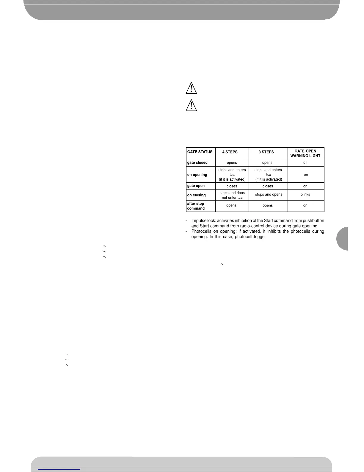
- 3-step or 4-step function logic: the Start command modifies the gate
status depending on whether the 3-step or 4-step logic is active, as
specified in the table below. The status of the gate-open warning light
is also specified.
!!
- Impulse lock: activates inhibition of the Start command from pushbutton
and Start command from radio-control device during gate opening.
- Photocells on opening: if activated, it inhibits the photocells during
opening. In this case, photocell triggering during opening is ignored.
Photocell triggering during closing causes the gate to stop and then
reopen. If not activated, photocell triggering on opening causes the gate
to stop and reopen once the obstacle has been removed.
- Gate-open or 2nd radio channel warning light: if activated, allows you to
connect a 24V warning light, as in figure 16. In this case the light
indicates the position of the gate as specified in the table above. If not
activated, the output to terminals 23 and 24 shows a current-free and
normally open contact, which is only activated for 1 second each time
key 2 is pressed on the associated radio-control device. Key 1 is
reserved for the Start command.
- Photocells not checked: if this setting is activated, it inhibits the photocell
checking function, allowing connection of devices not provided with
additional checking contact.
7) PROGRAMMING
7.1) Programming by means of the display
The display programmer available in the board allows you to set all the SCE
control panel functions.
Make reference to fig. A and B.
The predefined parameter is shown between square brackets [0].
The writing appearing on the display is indicated between round brackets.
Press the small OK key to display an introduction menu, press OK twice to
bypass this introduction. Now you enter a menu including the following
submenus: Parameters, logics, radio, language, default and self-diagnosis.
In the first 4 menus you can move up/down within each menu and enter the
submenus, then confirm the values set using the OK key. If you press OK
in the DEFAULT menu, you can reprogram the control unit with the factory-
set values. The SELF-DIAGNOSIS menu allows you to check the external
connections.
To go back and exit the programming function, simultaneously press the up/
down keys several times.
If, at the end of the diagnosis, the reply is OK, it means that the control unit
and connected devices work correctly.
7.2) Programming by means of UNIPRO
Connect the UNIPRO programmer to the control unit by means of the
UNIDA accessory (see fig. 26). The SCE control unit does not supply the
UNIPRO programmer, which therefore needs an appropriate supply unit.
Enter the “CONTROL UNITS” menu and the “PARAMETERS” submenu,
 Loading...