17) AUTOSET MENU (Autoset)
• Bring the door to its closing position.
• Initiate an autoset operation by moving to the appropriate SCE panel
menu (Fig.B).
• As soon as the OK button is pressed, the following message will be
displayed “.... .... ....”, and the control unit initiates an opening manoeuvre
followed by a closing manoeuvre, during which the minimum torque
value needed for door movement will be automatically set.
During this phase, it is important to avoid obscuring the photocells, as
well as using the START and STOP commands and the display.
• By the end of this operation, the control unit will have automatically set
the optimum torque values. Check and, if necessary, modify them as
described in the programming section.
WARNING: Check that the impact force value measured at the
points established by the EN 12445 standard is lower than that
specified in the EN 12453 standard.
WARNING! During the autoset phase, the obstacle detection
function is not optimised; the installer must check the operator
movement and prevent persons and things from coming near
or stopping within the operating range.
18) SLOW-DOWN SPEED AND TORQUE
N.B.: In the case where, during the final opening and closing phases, the
pushing force does not allow the required manoeuvre to be completed, the
gearmotor force can be increased by moving the transformer connection
from terminal 15V to terminal 20V, as in fig.20.
19) EMERGENCY MANOEUVRE
In case of electric power failure or system malfunction, the manoeuvre must
be carried out manually by pulling the wire connected to the carriage, as in
fig.21. For garages which are not provided with a second exit, it is
compulsory to fit an external key release device like Mod. SM1 (fig.22) or
Mod. SET/S (fig.23).
20) AUTOMATION CHECK
Before the automation device finally becomes operational,
scrupulously check the following conditions:
• Check that all the safety devices (limit microswitches, photocells,
electric edges etc) operate correctly.
• Check that the door (antisquash) thrust is comprised within the limits set
out by the current standards, and anyway not too strong for the
installation and operating conditions.
• Check that the chain-tightener spring is not completely compressed
during manoeuvre.
• Check the manual opening control operation.
• Check the opening and closing operations using the control
devices fitted.
• Check the normal and customised operation electronic logics.
21) AUTOMATION DEVICE USE
Since the automation device can be remotely controlled by means of a radio
control device or a Start button, and therefore when not in sight, all the
safety devices must be frequently checked in order to ensure their perfect
efficiency. In the event of any malfunction, request immediate assistance
from qualified personnel. Children must be kept at a safe distance from the
automation operation area.
22) AUTOMATION CONTROL
The use of this control device allows the gate to be opened and closed
automatically. There are different types of controls (manual, radio control,
magnetic card access etc.) depending on the installation requirements and
characteristics. For the various control systems, see the relevant instructions.
The automation device users must be instructed on control and operation.
23) MAINTENANCE
Before carrying out any maintenance operation, disconnect the system
power supply.
• Periodically check the tension of the belt (twice a year).
• Occasionally clean the photocell optical elements, if installed.
• Have a qualified technician (installer) check the correct setting of the
electronic clutch.
• When any operational malfunction if found, and not resolved,
disconnect the system power supply and request the assistance of a
qualified technician (installer). When the product is out of service,
activate the manual release device to allow the door to be opened
and closed manually.
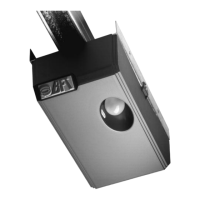
24) ACCESSORIES
SM1 External release device to be applied to the cremone bolt already
fitted to the overhead door (fig.22).
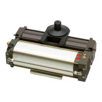
SET/S External release device with retracting handle for sectional doors
measuring max 50mm (fig.23).
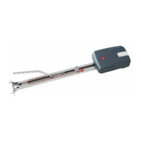
APT Extension and bracket accessories used to fit the product away
from the door or close to the ceiling (fig.24).
ST Automatic bolt release device for spring-operated overhead doors.
Fitted to the control arm, it automatically releases the side door
bolts (fig.25).
25) SCRAPPING
Warning! This operation should only be carried out by qualified personnel.
Materials must be disposed of in conformity with the current regulations.
In case of scrapping, the automation devices do not entail any particular
risks or danger. In case of materials to be recycled, these should be sorted
out by type (electrical components, copper, aluminium, plastic etc.).
26) DISMANTLING
Warning! This operation should only be carried out by qualified personnel.
When the automation system is disassembled to be reassembled on
another site, proceed as follows:
• Disconnect the power supply and the entire external electrical installation.
• In the case where some of the components cannot be removed or are
damaged, they must be replaced.
The descriptions and illustrations contained in the present manual
are not binding. The Company reserves the right to make any alterations
deemed appropriate for the technical, manufacturing and commercial
improvement of the product, while leaving the essential product
features unchanged, at any time and without undertaking to update
the present publication.