INSTALLATION MANUAL
1) FOREWORD
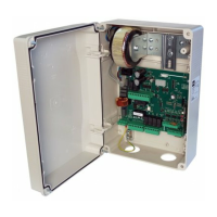
The RIGEL 5 control unit is supplied by the manufacturer with standard
setting. Any modications must be entered using the universal palmtop
programmer or the incorporated display. This Control unit supports the
entire EELINK protocol.
These are its main features:
- Control of one or two motors up to 600W power.
- Electronic torque setting.
- Adjustable electrodynamic braking.
- End-of-run speed slow-down.
- Separate opening / closing limit-switch inputs for each motor.
- Output for zone light.
- Separate inputs for safety devices.
- 12V output for click or suction-type electric lock.
- Output for timer piloting.
- Clock input.
- Connector for trac-light board / motor preheating.
- Incorporated radio receiver.
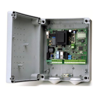
The board is provided with a removable terminal board for easier maintenance
and replacement. This is supplied with a series of prewired jumpers to make
work easy for the installer.
The jumpers relate to the following terminals: 33-34, 35-36, 36-37, 38-39,
39-40, 41-42, 42-43, 52-55. If the above terminals are used, remove the
respective jumpers.
2) TECHNICAL SPECIFICATIONS
CONTROL UNIT
Power supply 230V±10% 50Hz*
Mains/low voltage insulation
> 2MOhm 500V
Dielectric strength mains/bty 3750V~ for 1 minute
Motor output current 1A+1A max (230V
~
) - 2A+2A max
(110V
~
)
Motor relay commutation current 10A
Zone/courtesy light max 150W
Supply to accessories 24V~ (1A max absorption)
Electric lock
12V
(0.5A max, 2A for 3 s)
Light/alarm output with free n.o.
contact
max 3A 250V~
Gate-open warning light 24V~ 3W max
Blinker 230V 40W max
Fuses See Fig. A
Dimensions See Fig. B
RECEIVER
Commands association 1st ch. = start
2nd ch. = relay 2nd ch. for 1 sec.
Built-in Rolling-Code radio-re-
ceiver
frequency 433.92MHz
N° of combinations 4 billion
Max. n° of remotes that can be
memorized
63
Antenna impedance 50 Ohm (RG58)
(*) Special supply voltages to order.
Usable transmitter versions:
All ROLLING CODE transmitters compatible with
3) TUBE ARRANGEMENT Fig.A
Install the electrical system referring to the standards in force for electrical
systems CEI 64-8, IEC 364, harmonization document HD 384 and other
national standards.
----------------------------------------------------------
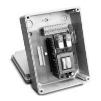
4) TERMINAL BOARD WIRING Fig. A
Once suitable electric cables have been run through the raceways and the
automated device’s various components have been fastened at the prede-
termined points, the next step is to connect them as directed and illustrated
in the diagrams contained in the relevant instruction manuals. Connect the
live, neutral and earth wire (compulsory). The mains cable must be clamped
in the relevant cable gland, and the accessories’ wires in the cable gland, while
the earth wire with the yellow/green-coloured sheath must be connected
in the relevant terminal.
TERMINAL
DESCRIPTION
1 GND terminal
2-3 230V~±10%, 50-60Hz power supply (2 neutral, 3 phase).
4-5-6
Motor connection 1 (delayed opening), terminals 5-6 for motor
drive, terminal 4 common.
5-14 Motor capacitor connection 1
7-8-9
Motor connection 2 (delayed closing), terminals 8-9 for motor
drive, terminal 7 common.
N.B. If only one motor is used, use motor output 2 and congure
logic “1 active motor”.
8-15 Motor capacitor connection 2.
10-11
230V~ output for blinker light (40W max) and EBP 230V mo-
delelectric lock. WARNING! If the SSR5 auxiliary board is used
for motor preheating, move the connection to terminals 12-13
(Fig. A) and refer to LOGIC TABLE “B” (Blinker output).
12-13
230V~ output for zone lighting (courtesy light dipswitch ON,
ashing light output dipswitch OFF)
230V~ output for courtesy light (courtesy light dipswitch OFF,
ashing light output dipswitch OFF)
230V~ output for ashing light output (ashing light dipswitch
ON)
16-17
Stair-light output (N.O.) (dip Light/alarm = OFF) Only connect
these terminals to safety extra low voltage (SELV) circuits suitably
insulated from live parts.
Light/alarm output (N.O.) (dip Light/alarm = ON). Only connect
these terminals to safety extra low voltage (SELV) circuits suitably
insulated from live parts.
18-19
N.O. output for 2nd radio channel (SCA dipswitch - 2ch =
OFF)
N.O. output for gate open warning light. This warning light is o
when the gate is closed, ashes as it is closing and remains on
when the gate is open or opening. (dipswitch SCA - 2ch = ON)
20-21 24V~ output (1A max.) to power accessories.
20-44 24V~ output to power VSAFE
22-23
12V
solenoid latch output (lock type dipswitch = OFF)
12V
solenoid sucker output (lock type dipswitch = ON)
24-25 Antenna input for radio receiver board (24 signal, 25 braid).
26-27
INTERNAL START Pushbutton (N.O.). Internal Start command
for trac light.
27-28
START Pushbutton (N.O.). Parallel to radio receiver relay (CH1).
External Start command for trac light.
27-29
PEDESTRIAN pushbutton (N.O.). Activation takes place on
motor 2; moreover, if the opening cycle has started (not from
pedestrian pushbutton), the pedestrian control has the same
eect as a Start command.
30-31 OPEN Pushbutton (N.O.).
30-32 CLOSE Pushbutton (N.O.).
33-34
LOCK pushbutton (N.C.). If not used, leave the jumper con-
nected.
35-36
Photocell contact input PHOT (n.c.). If not used, leave jumpers
inserted.
36-37
Photocell contact input PHOT OPENING (N.C.). If not used, leave
jumpers inserted. (dipswitch BAR = OFF)
BAR safety edge input (n.c.) If intervenes during opening, it
stops and we have partial closure. If not used, leave jumpers
inserted. (dipswitch BAR = ON)
38-39
Opening limit switch for motor 1 SWO1 (N.C.). If not used, leave
the jumper connected.
39-40
Closing limit switch for motor 1 SWC1 (n.c.). If not used, leave
the jumper connected.
41-42
Opening limit switch for motor 2 SWO2 (n.c.). If not used, leave
the jumper connected.
42-43
Closing limit switch for motor 2 SWC2 (n.c.). If not used, leave
the jumper connected.
20-44 24V output for transmitters.
45-46-47 Connection with tested safety devices (see Fig. D)
48-49-50 Connection with tested safety devices (see Fig. D)
20 - RIGEL 5
D811472 00100_01

 Loading...