D812939 00096_03
VIRGO SMART BT A - 47
ENGLISH
INSTALLATION MANUAL
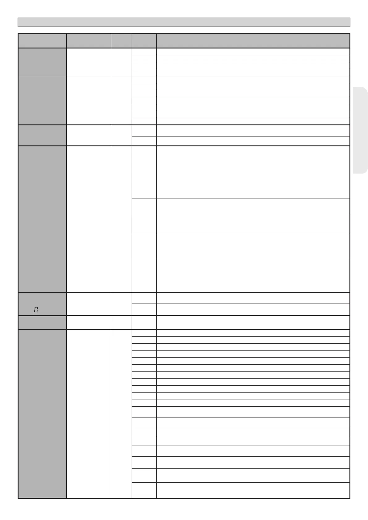
Logic Denition
Default
Cross out
setting
used
Optional extras
AUX 0
Conguration of
AUX 0 output. 20-21
6
0 Output congured as 2nd Radio Channel.
1 Output congured as SCA (gate open light).
2 Output congured as Courtesy Light command.
3 Output congured as Zone Light command.
AUX 3
Conguration of
AUX 3 output.
26-37
0
4 Output congured as Stair Light
5 Output congured as Alarm
6 Output congured as Flashing light
7 Output congured as Latch
8 Output congured as Magnetic lock
9 Output congured as Maintenance
10 Output congured as Flashing Light and Maintenance.
FIXED CODE
Fixed code
0
0
Receiver is congured for operation in rolling-code mode.
Fixed-Code Clones are not accepted.
1
Receiver is congured for operation in xed-code mode.
Fixed-Code Clones are accepted.
Protection
level
Setting the
protection level
0
0
A - The password is not required to access the programming menus
B - Enables wireless memorizing of transmitters.
Operations in this mode are carried out near the control panel and do not require access:
- Press in sequence the hidden key and normal key (T1-T2-T3-T4) of a transmitter that has already been
memorized in standard mode via the radio menu.
- Press within 10 sec. the hidden key and normal key (T1-T2-T3-T4) of a transmitter to be memorized.
The receiver exits programming mode after 10 sec.: you can use this time to enter other new transmitters
by repeating the previous step.
C - Enables wireless automatic addition of clones.
Enables clones generated with the universal programmer and programmed Replays to be added to the
receiver’s memory.
D - Enables wireless automatic addition of replays.
Enables programmed Replays to be added to the receiver’s memory.
E - The board’s parameters can be edited via the U-link network
1
A - You are prompted to enter the password to access the programming menus
The default password is 1234.
No change in behaviour of functions B - C - D - E from 0 logic setting
2
A - You are prompted to enter the password to access the programming menus
The default password is 1234.
B - Wireless memorizing of transmitters is disabled.
C - Wireless automatic addition of clones is disabled. No change in behaviour of functions D - E from 0 logic
setting
3
A - You are prompted to enter the password to access the programming menus
The default password is 1234.
B - Wireless memorizing of transmitters is disabled.
D - Wireless automatic addition of Replays is disabled.
No change in behaviour of functions C - E from 0 logic setting
4
A - You are prompted to enter the password to access the programming menus
The default password is 1234.
B - Wireless memorizing of transmitters is disabled.
C - Wireless automatic addition of clones is disabled.
D - Wireless automatic addition of Replays is disabled.
E - The option of editing the board’s parameters via the U-link network is disabled.
Transmitters are memorized only using the relevant Radio menu.
IMPORTANT: This high level of security stops unwanted clones from gaining access and also stops radio
interference, if any.
SERIAL
ODE
Serial mode
(Identies how board
is congured in a BFT
network connection).
0
0 Standard SLAVE: board receives and communicates commands/diagnostics/etc.
1 Standard MASTER: board sends activation commands (START, OPEN, CLOSE, PED, STOP) to other boards.
ADDRESS
Address 0
[ ___ ]
Identies board address from 0 to 119 in a local BFT network connection.
(see U-LINK OPTIONAL MODULES section)
EXPI1
Conguration of
EXPI1 input on
input-output expan-
sion board.
1-2
1
0 Input congured as Start E command.
1 Input congured as Start I command.
2 Input congured as Open command.
3 Input congured as Close command.
4 Input congured as Ped command.
5 Input congured as Timer command.
6 Input congured as Timer Pedestrian command.
7 Input congured as Phot (photocell) safety.
8 Input congured as Phot op safety (photocell active during opening only).
9 Input congured as Phot cl safety (photocell active during closing only).
10 Input congured as Bar safety (safety edge).
11
Input congured as safety Bar OP, safety edge with inversion active only while opening, if while closing
the movement stops.
12
Input congured as safety Bar CL, safety edge with inversion active only while closing, if while opening
the movement stops.
13
Input congured as Phot test safety, tested photocell. Input 3 (EXPI2) on input/output expansion board is
switched automatically to safety device test input, EXPFAULT1.
14
Input congured as Phot op test safety, tested photocell active only while opening. Input 3 (EXPI2) on input/
output expansion board is switched automatically to safety device test input, EXPFAULT1
15
Input congured as Phot cl test safety, tested photocell active only while closing. Input 3 (EXPI2) on input/
output expansion board is switched automatically to safety device test input, EXPFAULT1
16
Input congured as Bar safety, tested safety edge. Input 3 (EXPI2) on input/output expansion board is
switched automatically to safety device test input, EXPFAULT1.
17
Input congured as safety Bar OP test, safety edge with inversion active only while opening, if while closing
the movement stops. Input 3 (EXPI2) on input/output expansion board is switched automatically to safety
device test input, EXPFAULT1.
18
Input congured as safety Bar CL test, safety edge with inversion active only while closing, if while opening
the movement stops. Input 3 (EXPI2) on input/output expansion board is switched automatically to safety
device test input, EXPFAULT1.

 Loading...