D812939 00096_03
44 - VIRGO SMART BT A
INSTALLATION MANUAL
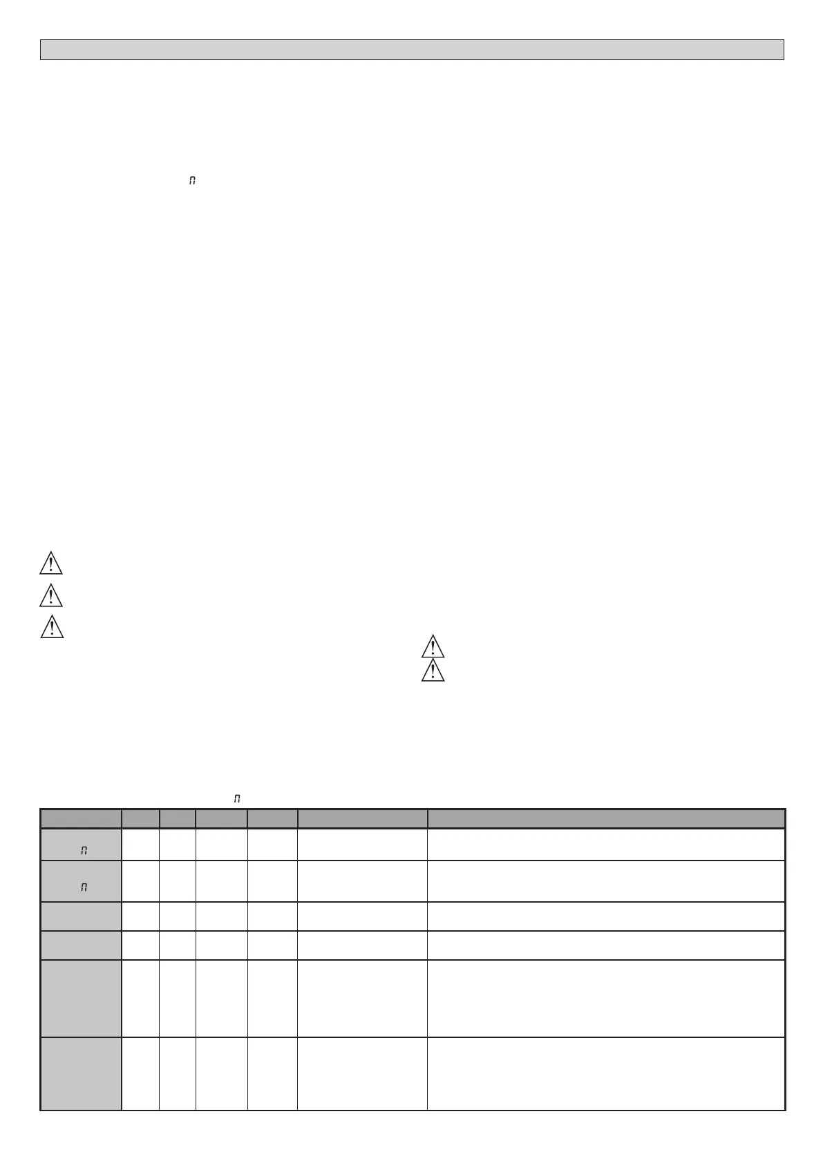
TABLE “A” PARAMETERS MENU - PARA
Parameter min. max. Default
Personal
Denition Description
OPEN DELAY
TI
E
0 10 3
Motor 2 opening delay
time [s]
Motor 2 opening delay time with respect to motor 1.
CLS DELAY
TI E
0 25 6
Motor 1 closing delay
time [s]
Motor 1 closing delay time with respect to motor 2.
NOTE: if the time is set to maximum, before starting, engine 1 waits for the
complete shut down of engine 2.
TCA
0 120 10
Automatic closing time
[s]
Waiting time before automatic closing.
TRF.LGHT.CLR.T
1 180 40
Time-to-clear trac light
zone [s]
Time-to-clear for the zone run through by trac controlled by the trac light.
OP.DIST.SLOUD
0 50 10
Slow-down distance
during opening [%]
Slow-down distance for motor(s) during opening, given as a percentage
of total travel. WARNING: Once the parameter has been edited, a
complete uninterrupted opening-closing cycle is required.
WARNING: when the display reads “SET”, obstacle detection is not active.
ATTENTION: with actuators with integrated locks, the permanently active
slowdown to a value higher than 5 is mandatory.
WARNING: in GIUNO, the slow-down distance is set with the sliding sensors
CL.DIST.SLOUD
0 50 10
Slow-down distance
during closing [%]
Slow-down distance for motor(s) during closing, given as a percentage
of total travel. WARNING: Once the parameter has been edited, a
complete uninterrupted opening-closing cycle is required.
WARNING: when the display reads “SET”, obstacle detection is not active.
ATTENTION: with actuators with integrated locks, the permanently active
slowdown to a value higher than 5 is mandatory.
WARNING: in GIUNO, the slow-down distance is set with the sliding sensors
6) SAFETY DEVICES
Note: only use receiving safety devices with free changeover contact.
6.1) TESTED DEVICES Fig. M
6.2 CONNECTION OF 1 PAIR OF NONTESTED PHOTOCELLS FIG. L
7 CALLING UP MENUS: FIG. 2
7.1) PARAMETERS MENU PARA PARAMETERS TABLE “A”
7.2) LOGIC MENU LOGIC LOGIC TABLE “B”
7.3) RADIO MENU radio RADIO TABLE “C”
- IMPORTANT NOTE: THE FIRST TRANSMITTER MEMORIZED MUST BE
IDENTIFIED BY ATTACHING THE KEY LABEL (MASTER).
In the event of manual programming, the rst transmitter assigns the RECEIVER’S
KEY CODE: this code is required to subsequently clone the radio transmitters.
The Clonix built-in on-board receiver also has a number of important advanced features:
• Cloning of master transmitter (rolling code or xed code).
• Cloning to replace transmitters already entered in receiver.
• Transmitter database management.
• Receiver community management.
To use these advanced features, refer to the universal handheld programmer’s
instructions and to the general receiver programming guide.
7.4 DEFAULT MENU default
Restores the controller’s DEFAULT factory settings. Following this reset, you will
need to run the AUTOSET function again.
7.5 LANGUAGE MENU language
Used to set the programmer’s language on the display.
7.6 AUTOSET MENU AUTOset
•
Launch an autoset operation by going to the relevant menu.
•
As soon as you press the OK button, the “.... .... ....” message is displayed and the control
unit commands the device to perform a full cycle (opening followed by closing), during
which the minimum torque value required to move the leaf is set automatically.
The number of cycles required for the autoset function can range from 1 to 3.
During this stage, it is important to avoid breaking the photocells’ beams and not
to use the START and STOP commands or the display.
Once this operation is complete, the control unit will have automatically set the
optimum torque values. Check them and, where necessary, edit them as described
in the programming section.
WARNING!! Check that the force of impact measured at the points
provided for by standard EN 12445 is lower than the value laid down
by standard EN 12453.
Impact forces can be reduced by using deformable edges.
Warning!! While the autoset function is running, the obstacle detection
function is not active. Consequently, the installer must monitor the
automated system’s movements and keep people and property out
of range of the automated system.
7.7)INSTALLATION TEST PROCEDURE
1. Run the AUTOSET cycle (*)
2. Check the impact forces: if they fall within the limits (**) skip to point 10 of the
procedure, otherwise
3. Where necessary, adjust the speed and sensitivity (force) parameters: see
parameters table.
4. Check the impact forces again: if they fall within the limits (**) skip to point 10
of the procedure, otherwise
5. Apply a shock absorber prole
6. Check the impact forces again: if they fall within the limits (**) skip to point 10
of the procedure, otherwise
7. Apply pressure-sensitive or electro-sensitive protective devices (such as a
safety edge) (**)
8. Check the impact forces again: if they fall within the limits (**) skip to point 10
of the procedure, otherwise
9. Allow the drive to move only in “Deadman” mode
10. Make sure all devices designed to detect obstacles within the system’s operating
range are working properly
(*) Before running the autoset function, make sure you have performed all the
assembly and make-safe operations correctly, as set out in the installation
warnings in the drive’s manual.
(**) Based on the risk analysis, you may nd it necessary to apply sensitive
protective devices anyway
7.8 STATISTICS MENU
Used to view the version of the board, the total number of operations (in
hundreds), the number of transmitters memorized and the last 30 errors (the
rst 2 digits indicate the position, the last 2 give the error code). Error 01 is the
most recent.
7.9) PASSWORD MENU
Used to set a password for the board’s wireless programming via the U-link
network. With “PROTECTION LEVEL” logic set to 1,2,3,4, the password is required
to access the programming menus. After 10 consecutive failed attempts to
log in, you will need to wait 3 minutes before trying again. During this time,
whenever an attempt is made to log in, the display will read “BLOC”. The default
password is 1234.
8) CLOSING LIMIT SWITCH PRESSURE Fig. O Ref. A-B
OPENING DIRECTION Fig. J
9) CONNECTION WITH EXPANSION BOARDS AND UNIVERSAL HANDHELD
PROGRAMMER (Fig. N) Refer to specic manual.
10) U-LINK OPTIONAL MODULES
Refer to the U-link instructions for the modules.
The use of some models causes lowered radio capacity. Adjust the system using an
appropriate antenna tuned to 433MHxz.
11) RESTORING FACTORY SETTINGS FIg.P
WARNING: this operation will restore the control unit’s factory settings and all
transmitters stored in its memory will be deleted.
WARNING! Incorrect settings can result in damage to property and injury to
people and animals.
- Cut o power to the board (Fig.P ref.1)
- Open the Stop input and press the - and OK keys together (Fig.P ref.2)
- Switch on the board’s power (Fig.P ref.3)
- The display will read RST; conrm within 3 sec. by pressing the OK key (Fig.P ref.4)
- Wait for the procedure to nish (Fig.P ref.5)
- Procedure nished (Fig.P ref.6)
WARNING! Incorrect settings can result in damage to property and injury to people
and animals.
WARNING: Check that the force of impact measured at the points
provided for by standard EN 12445 is lower than the value laid down
by standard EN 12453.
Impact forces can be reduced by using deformable edges.
For best results, it is advisable to run the autoset function with the motors idle (i.e.
not overheated by a considerable number of consecutive operations).

 Loading...