D812939 00096_03
VIRGO SMART BT A - 45
ENGLISH
INSTALLATION MANUAL
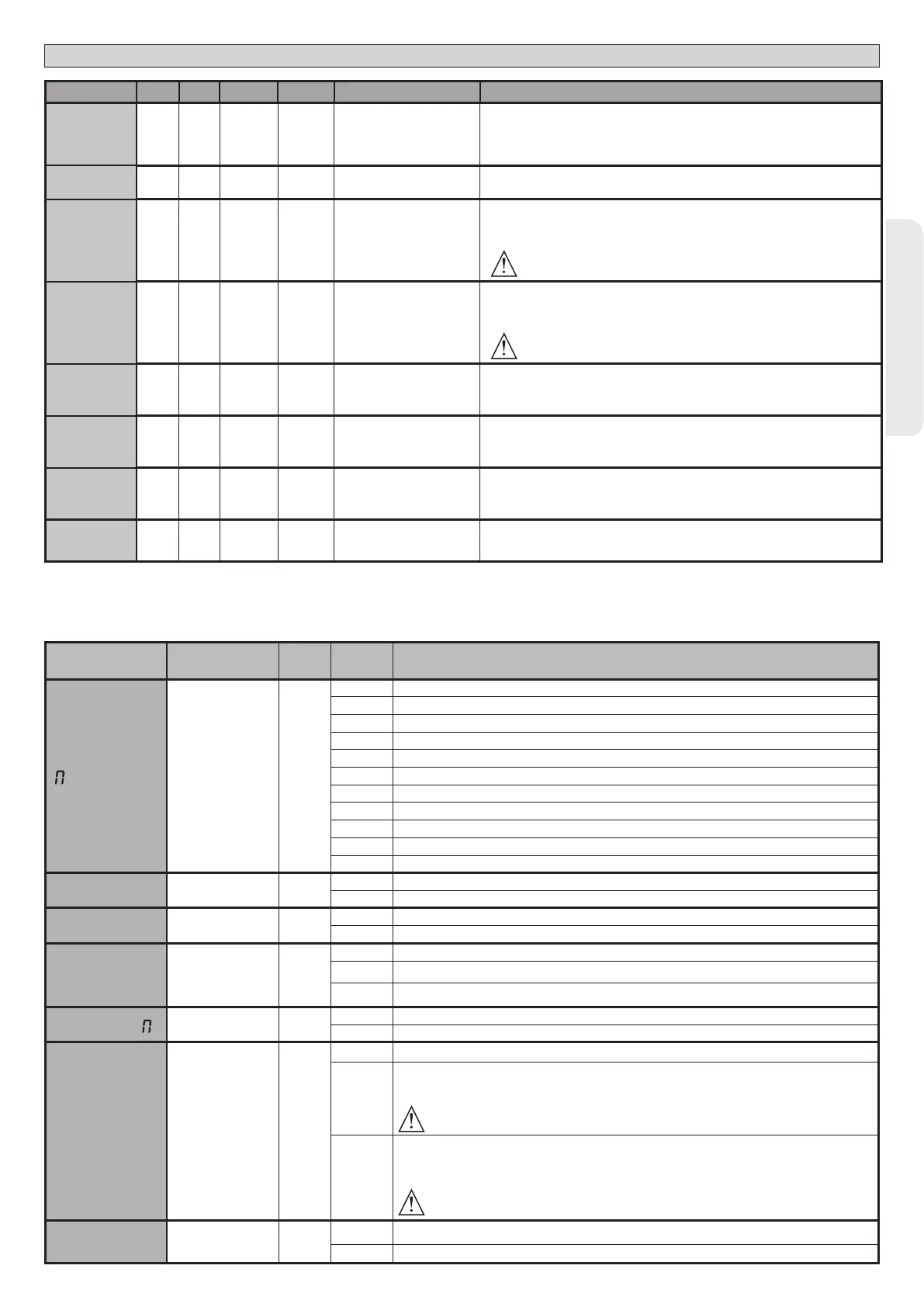
Parameter min. max. Default
Personal
Denition Description
DIST.DECEL
0 50 15
Deceleration distance
[%]
Deceleration distance (switch from running speed to slow-down
speed) for motor(s) both during opening and during closing, given as a
percentage of total travel. WARNING: Once the parameter has been
edited, a complete uninterrupted opening-closing cycle is required.
WARNING: when the display reads “SET”, obstacle detection is not active.
PARTIAL
OPENING
10 99 99 Partial opening M1 [%]
Partial opening distance as a percentage of total opening following activation
of PED pedestrian command.
OP.FORCE
1 99 50
Leaf force during
opening [%]
Force exerted by leaf/leaves during opening. This is the percentage of force
delivered, beyond the force stored during the autoset cycle (and subsequently
updated), before an obstacle alarm is generated.
The parameter is set automatically by the autoset function.
WARNING: It aects impact force directly: make sure that current
safety requirements are met with the set value (*). Install anti-
crush safety devices where necessary (**).
CLS.FORCE
1 99 50
Leaf force during
closing [%]
Force exerted by leaf/leaves during closing. This is the percentage of force
delivered, beyond the force stored during the autoset cycle (and subsequently
updated), before an obstacle alarm is generated.
The parameter is set automatically by the autoset function.
WARNING: It aects impact force directly: make sure that current
safety requirements are met with the set value (*). Install anti-
crush safety devices where necessary (**).
OP SPEED
15 99 99 Opening speed [%}
Percentage of maximum speed that can be reached by motor(s) during
opening. WARNING: Once the parameter has been edited, a complete
uninterrupted opening-closing cycle is required. WARNING: when the
display reads "SET", obstacle detection is not active.
CL SPEED
15 99 99 Closing speed [%]
Percentage of maximum speed that can be reached by motor(s) during
closing. WARNING: Once the parameter has been edited, a complete
uninterrupted opening-closing cycle is required. WARNING: when the
display reads "SET", obstacle detection is not active.
SLOW SPEED
15 99 25 Slow-down speed [%]
Opening and closing speed of motor(s) during slow-down stage, given as a
percentage of maximum running speed. WARNING: Once the parameter has
been edited, a complete uninterrupted opening-closing cycle is required.
WARNING: When the display reads “”SET””, obstacle detection is not active.
Maintenance
0 250 0
Programming number of
operations for maintenan-
ce threshold
[in hundreds]
Allows you to set a number of operations after which the need for mainte-
nance will be reported on the AUX output congured as Maintenance or
Flashing Light and Maintenance .
(*) In the European Union, apply standard EN 12453 for force limitations, and standard EN 12445 for measuring method.
(**) Impact forces can be reduced by using deformable edges.
TABLE “B” LOGIC MENU - logic
Logic Denition
Default
Cross out
setting
used
Optional extras
otor type
Motor type
(Set the type of motor
connected to the
board).
0
0 Motors not active
1 ELI 250 BT - Do not use
2 PHOBOS N BT - Do not use
3 IGEA BT - Do not use
4 LUX BT - Do not use
5 LUX G BT - Do not use
6 SUB BT - Do not use
7 KUSTOS BT A - PHOBOS BT A - Do not use
8 GIUNO ULTRA BT A 20 - GIUNO ULTRA BT A50 - Do not use
9 VIRGO SMART BT A - 5 wires
10 VIRGO SMART BT A - 3 wires
TCA
Automatic Closing
Time
0
0 Logic not enabled
1 Switches automatic closing on
FAST CLS.
Fast closing 0
0 Logic not enabled
1 Closes 3 seconds after the photocells are cleared before waiting for the set TCA to elapse.
STEP-BY-
STEP MO-
VEMNT
Step-by-step
movement
0
0 Inputs congured as Start E, Start I, Ped operate with 4-step logic.
1
Inputs congured as Start E, Start I, Ped operate with 3-step logic. Pulse during closing reverses move-
ment.
2 Inputs congured as Start E, Start I, Ped operate with 2-step logic. Movement reverses with each pulse.
PRE-ALAR
Pre-alarm 0
0 The ashing light comes on at the same time as the motor(s) start.
1 The ashing light comes on approx. 3 seconds before the motor(s) start.
HOLD-TO-
RUN
Deadman 0
0 Pulse operation.
1
Deadman mode.
Input 61 is congured as OPEN UP.
Input 62 is congured as CLOSE UP.
Operation continues as long as the OPEN UP or CLOSE UP keys are held down.
WARNING: safety devices are not enabled.
2
Emergency Deadman mode. Usually pulse operation.
If the board fails the safety device tests (photocell or safety edge, Er0x) 3 times in a row, the device is
switched to Deadman mode, which will stay active until the OPEN UP or CLOSE UP keys are released.
Input 61 is congured as OPEN UP.
Input 62 is congured as CLOSE UP.
WARNING: with the device set to Emergency Deadman mode, safety devices are not enabled.
IBL OPEN
Block pulses during
opening
0
0 Pulse from inputs congured as Start E, Start I, Ped has eect during opening.
1 Pulse from inputs congured as Start E, Start I, Ped has no eect during opening.

 Loading...