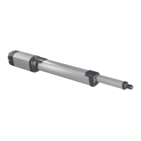
2) GENERAL OUTLINE
Low-voltage operator (24V
) suitable for residential use. Designed for
swing gates having small-sized pillars. The operating arm, with its special
antishearing shape, allows the leaves to be manoeuvred even when the
operator is positioned well away from their fulcrum. The irreversible
electromechanical gearmotor keeps the gate locked in the closing and
opening positions.
The release lever, tted to the outside of each operator, allows the manual
manoeuvre to be carried out very easily.
ATTENTION! The VIRGO model controller is not equipped with mecha-
nical torque adjustment. It is compulsory to use a control panel of the
same manufacturer, in compliance with the basic safety requirements
of directives 2006/95/CEE, 2004/108/CEE, 2006/42/CEE equipped with
appropriate electric adjusment of the torque.
Before carrying out the manual manoeuvre make sure that this operation
will not create a dangerous situations.
Check in the relevant literature that the thermal eld in the working area
is suitable for the operator.
Make sure that the movement of the door does not cause entrapment
risks between the movable and xed parts of the door.
If swing gates with built-in doors are used, the motor must not run when
the door is left open.
WARNING! The operator must be installed by a qualied technician as
special safety components are used for every specic site and therefore
safety depends on installation.
3) TECHNICAL SPECIFICATIONS
3.1) VIRGO OPERATOR
Motor: ..........................................................................................24V
2500 min
-1
Power: .................................................................................................................. 110W
Insulation class: .......................................................................................................... F
Lubrication: ................................................................................ Permanent grease
Reduction ratio: .............................................................................................. 1-1224
Output shaft revolutions: .................................................................2 min
-1
MAX
Opening time 90°: ................................................................................................ 14s
Torque supplied: ..........................................................................................170 Nm
Max leaf weight and length: ....................2000N (~200kg) for 2m long leaf
Impact reaction: ......................................................... Integrated torque limiter
.................................................................................................on LINX control panel
Motion drive: ............................................................................................. Lever arm
Stop: ................ Incorporated electrical limit switches + mechanical locks
Manual manoeuvre: ...............................................Release lever with CLS key
Number of manoeuvres in 24h: ........................................................................ 60
Environmental conditions: ................................................... from -15 to +50 °C
Degree of protection:........................................................................................ IPX4
Operator weight: ......................VIRGO:80N (~8kg) - VIRGO SQ:60N (~6kg)
Dimensions: ................................................................................................... see g.1
3.2) LINX CONTROL PANEL
Power supply: ....................................................................... 230V~ ±10% 50Hz*
Mains/low voltage insulation: ............................................> 2MOhm 500Vdc
Working temperature ............................................................from -15 to +50 °C
Dielectric strength: ....................................... mains/l.v. 3750V~ for 1 minute
Motor output current: .................................................................3.5A+3.5A max
Motor relay commutation current: .............................................................. 10A
Maximum motor power: ...............................................................110W (24V
)
Power supply for accessories: ...................24V~ (180mA max absorption)
......................................................................24V~ safe (180mA max absorption)
Gate-open warning light: .................................N.O. contact (24V~/1A max)
Blinker: ..............................................................................................24V~ 25W max
Dimensions: ...........................................................................................see gure 1
Fuses: ........................................................................................................ see g.9-15
(*other voltages available on request)
3.3) VIRGO BAT BATTERY KIT (OPTIONAL - Fig.14)
Allows operation to continue even when the mains power supply is o
for a short time.
Charge voltage: .............................................................27.2V
Charge cur-
rent: ...................................................................................................................130mA
Data detected with external temperature of: ......................................... 25°C
Battery capacity: .............................................................................2x (12V 1.2Ah)
Exhausted battery protection threshold: ..........................................20.4V
Battery recharge time: ............................................................................... 12/14 h
NOTE: In case of operation with battery back up, the outputs to termi-
nals 8-9 (Vsafe 24V~) and 10-11 (Vsafe 24V~) show a voltage of 24V
polarised as indicated in Fig.16.
At the time of installing the VIRGO BAT Kit, check that the safety devices
are connected correctly.
4) OPERATOR INSTALLATION
4.1) Preliminary checks
Check that:
• Thegatestructureissucientlysturdyandrigid.
The xing position must be worked out according to the leaf structu-
re. In any case, the manoeuvring arm must push against a reinforced
leaf point.
• Theleavescanbemovedmanuallyalongtheirentirestroke.
If the gate has not been installed recently, check the wear condition of
all its components. Repair or replace defective and worn parts.
Operator reliability and safety are directly aected by the condition
of the gate structure.
5) SUPPORT PLATE FIXING (Fig.5)
The operator is supplied with a xing bracket and lever arm.
Having identied the leaf reinforcement point, with the gate closed,
trace an imaginary horizontal line from the centre of the reinforcement
point to the pillar (g. 3-4).
Fig. 2 illustrates the most common types of installation:
- with the leaf hinge pivot not aligned with the xing plate (90° opening
- maximum distance between hinge pivot and plate: 210mm).
- with the hinge pivot aligned with the xing plate
Position the anchoring bracket observing the dimensions shown in g.3
for opening up to 90°, or in g.2-4 for opening over 90° up to a max of 120°.
Thepillarsurface,wherethebracketisxed,mustbeatandparallel
to the leaf. Use screws and expansion plugs adequate for the type of
pillar. In the case where the pillar surface is irregular, use expansion
plugs with studs, in order to be able to adjust the xing bracket parallel
to the leaf (g.5).
• Assembletheleverarmasing.7.
DX = tting to right leaf
SX = tting to left leaf
Choose the most suitable position for xing bracket “F” to the leaf.
• InsertleverLintothegearmotoroutputshaft,andxitusingappro-
priate pivot P and self-locking nut D (g.7).
• Releasetheoperatorbyactivatingthereleaselevertoallowthearm
to move easily (see paragraph “EMERGENCY MANOEUVRE”).
• OpenthegearmotorcoverandxittotheplateasindicatedinFig.8.
• Fixtowinganglebar“F”totheleaf.
• Thecorrectpositionfortheoperatorarmisillustrateding.6.Theleaf
attachment point can be identied by positioning the arm according
to the dimension indicated in g.6.
• Withtheoperatorreleased,checkthearmforcorrectmovement.
• Repeatthesameprocedurefortheotherleaf.
6) BACKSTOP FIXING
The VIRGO operator is provided with mechanical end-of-stroke backstops,
which make the installation of ground stop plates redundant.
With reference to Fig. 10 proceed as follows:
- Identify the opening and closing end-of-stroke points and x the
backstops accordingly.
- Fix protection cover C.
7) ELECTRICAL INSTALLATION SET-UP
Arrange the electrical installation as shown in g.11.
Keep the mains voltage connections denitely separate from the very
low voltage connections (24V).
For this purpose, the operator is provided with appropriate ttings, indicated
inFig.9,foraspiralexibleracewaywithaninsidediameterof20:
- P1 input for mains power supply + GND.
- P2/P3 inputs for safety devices and accessories.
For the mains power supply, use the appropriate cable clamp (Fig.9 -”S”),
the terminal bar with an incorporated protection fuse (Fig.9 -”L-N”) and
the GND terminal.
Connect the yellow/green cable to the earth terminal.
Fig.16 shows the cross-section and the number of connections.
18 - VIRGO

 Loading...