SW-Stahl und Werkzeugvertriebs GmbH Tel. +49 (0) 2191 / 46438-0
F 56 essartS resukreveL ax +49 (0) 2191 / 46438-40
ed.lhatsws@ofni :liaM-E diehcsmeR 79824-D
Instruction Manual
BGS technic KG
Bandwirkerstr. 3
42929 Wermelskirchen
Tel.: 02196 720480
Fax.: 02196 7204820
mail@bgs-technic.de
www.bgstechnic.com
© BGS technic KG, Copying and further use not allowed
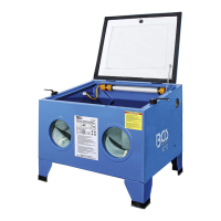
OPERATE
1. Place the sand blast cabinet near a 230V/60Hz AC electrical outlet. Make sure the receptacle will
accept the 3 -prong plug so that the unit will be properly grounded. Also make sure to check the
power source is adequate for use with this blast system.
2. Attach the air supply line from a compressor capable of maintaining 5 CFM at 80 PSI to the inlet
connector found on the right side of the cabinet. Because of variation in air supply systems, the air
inlet coupling is not provided. Use the particular fitting that is compatible with your air supply
system. Do not operate the blasting system at over 100 psi.
3. Check the air supply line fittings and hose attachments to the rear of the gun. Also make sure the
media supply hose is attached lightly on the nipple on the underside of the gun.
4. Place no more than 10 pounds of abrasive media into the center of the cabinet. Excessive
amounts will create clouded cabinet conditions, blow by media through the exhaust or sluggish
and ineffective blasting performance.
5. With the air supply connected, all fittings and joints not leaking and the unit is plugged in. You are
ready to test the blasting system. Now follow these steps for start up operation.
6. Place the part in the cabinet. Always close and latch the lid after placing the part in the cabinet
prior to blasting. Severe injury to the skin and eyes may result from exposure to the blast stream.
After pulling your hands into the gloves grasp the gun and depress the trigger. This should begin
the blasting flow. If no flow is seen you may need to clear the tube by covering the gun nozzle
momentarily.
7. Now you may begin finishing the part. You should move the blast stream continuously over the
part in an even and circular motion. The flow should not be too hard or concentrated to avoid
undesirable peening.
PARTS
Transparent Top Lid
RF LR Leg
1/4” Hose Clamp
Top Lid Position Chain
Screw 1/4x3/8"
Glove Clamp
Screw
Screw 5/32x3/8"
Glove
Nut
Nut 5/32"
Self Drilling Screw
Movable Leaf
Nut
Screw
Plastic Screw
Sanding Gun
Air cleaner
Front Panel
Nozzle
Filter
Rear Panel
Air Supply Hose
Anchor Plate
Right Panel
Plastic Suction Hose
Lamp
Left Panel
Steel Suction Hose
Feed thru
Base
Air Hose Connector
Wire Connector Box
Lamp Clamp
Washer
AC-AC Adaptor
LF RR Leg
Air Supply Connector