EasyManua.ls Logo

Biasi Riva Plus - Room Thermostat Connection; Relay Panel Connection

Biasi Riva Plus
52 pages
Print Icon
To Next Page IconTo Next Page
To Previous Page IconTo Previous Page
Loading...
Riva Plus Manual
30
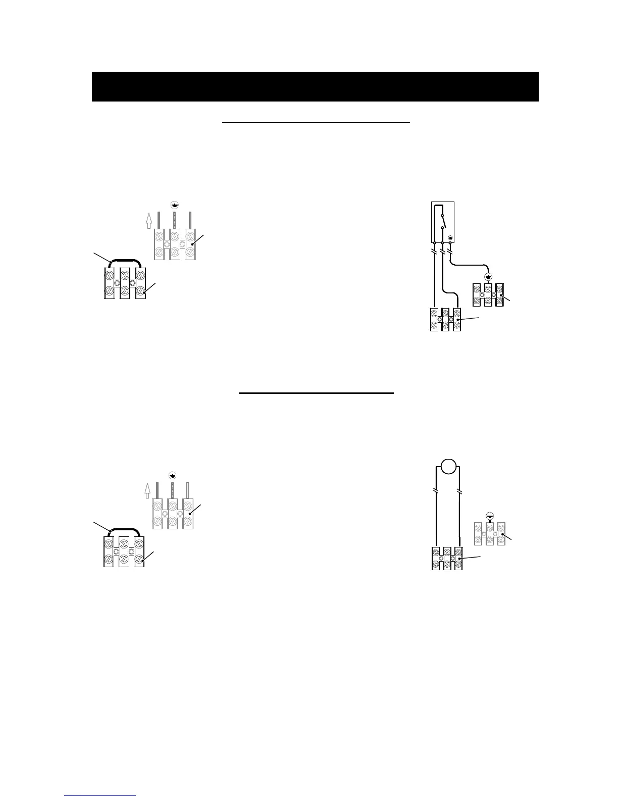
12.3 Room Thermostat Connection:
• The room thermostat
must be connected to
the terminal block
situated next to the
control panel.
12
L
N
3
To fused spur
isolation switch
Power supply
terminal block
External controls
terminal block
J
120 VAC Control
Terminal Block
Figure 12.6
• Any external controls
and connection lines
must be rated at 120
VAC but under no
circumstances should
external live voltage
be connected to the
room thermostat link
on the boiler.
• When connecting any
type of external
control, the jumper J
in Fig. 12.6 must be
removed.
• The room thermostat
must be connected to
the “Control Terminal
Block” (Fig 12.7).
•
• Connect the room
thermostat between
terminals 1 and 3 as
shown in Fig. 12.7.
Power supply
terminal block
External controls
terminal block
T
Room thermostat
12
L N
3
(120V rating)
Figure 12.7
12.4 Relay Panel Connection:
• The relay control must
be connected to the
terminal block situated
next to the control
panel.
12
L
N
3
To fused spur
isolation switch
Power supply
terminal block
External controls
terminal block
J
120 VAC Control
Terminal Block
Figure 12.8
• When connecting any
type of relay control,
the jumper J in Fig.
12.8 must be removed.
• Connect the dry
contact switch of the
relay panel to the 120
VAC control terminal
block (Fig 12.9).
•
• Connect the dry
contact switch to
terminals 1 and 3
shown in Fig. 12.9.
Power supply
terminal block
External controls
terminal block
Generic Relay Control
12
L N
3
(120V rating)
T
Figure 12.9
12. Electrical Connections/Wiring
Cont.