Riva Plus Manual
40
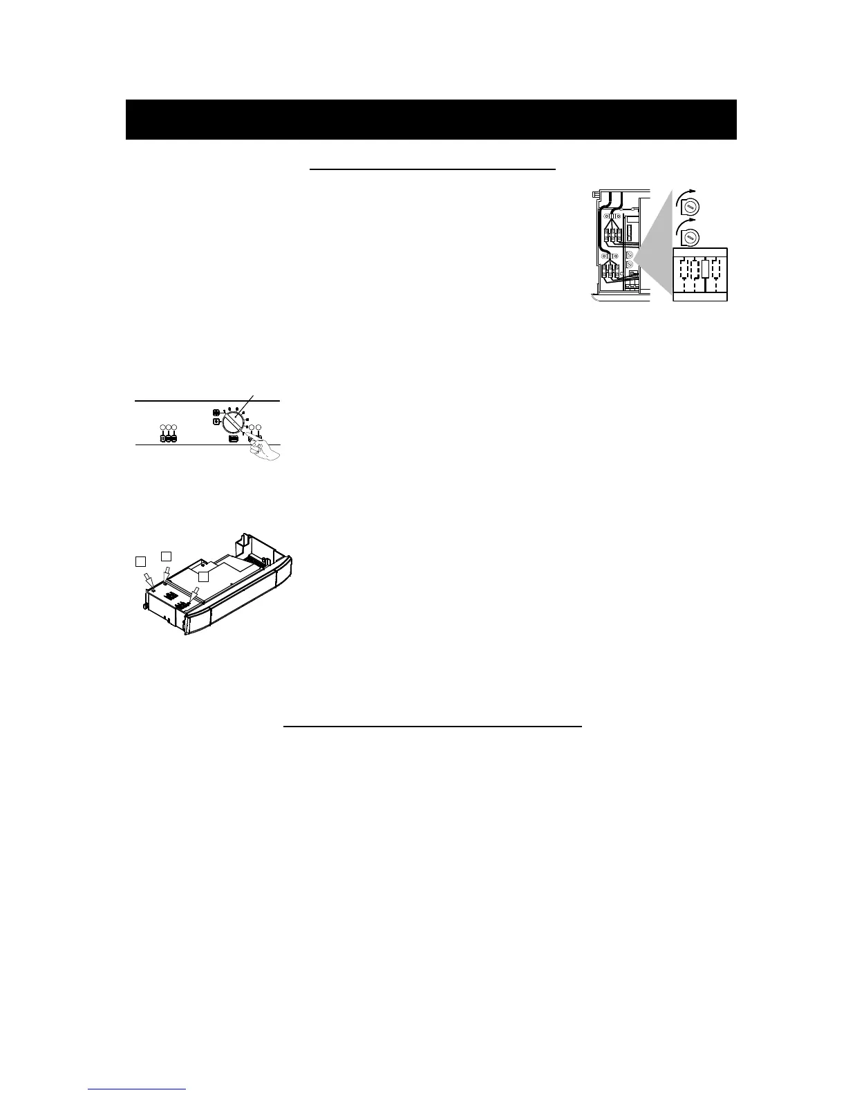
15.6 Checking the burner ignition:
• Turn the boiler OFF.
• Open the gas valve outlet
pressure test point 15
(figure 15.5) and connect
the gauge.
• Turn the boiler ON
positioning the function
selector B in the position
shown in figure 15.7 and
ensure that the room
thermostat is set to “heat
demand”.
B
Figure 15.7
• Loosen screws D and
remove the service panel
(figure 15.8).
D
D
D
Figure 15.8
• Watch the gauge and
check to see if the ignition
pressure registerd
corresponds to the values
given in the Technical
Data. Turn off the boiler
and reignite it by turning
the function selector B to
the 0 position and then
back to that indicated in
figure 15.7.
• Repeat this process two to
three times leaving 30
second intervals between
each ignition. Check the
ignition pressures and
visually check that the
burner lights uniformly and
in a controlled manner.
• To carry out the
adjustment move the
function selector 3 to the
OFF position (Fig. 15.9)
and use the device (ACC).
2 3
4
OFF
ON
1
ACC
RISC
+
Figure 15.9
• Adjust the gas pressure at
the injectors to the value
indicated in the tables of
section 2. By rotating the
device clockwise the
pressure increases.
• After the adjustment
operations bring the
selector 3 of figure 15.9
back to the normal position
(ON).
• Reassemble the service
panel.
• Close the gas valve outlet
pressure test point 15
(figure 15.5).
• Reassemble the front
pannel of the case.
Important: after the
checks all of the test
points must be sealed.
15.7 Adjustment of the useful c.h. output:
• Turn the boiler OFF.
• Open the gas valve outlet
pressure test point 15
(figure 15.5) and connect
the gauge.
• Turn the boiler ON
positioning the function
selector B in the position
shown in figure 15.7 and
ensure that the room
thermostat is set to “heat
demand”.
• Loosen screws D and
remove the service panel
(figure 15.8).
• To carry out the
adjustment use the
adjustment device (RISC)
with the help of a
screwdriver.
• By rotating the device
clockwise the pressure
increases.
• Adjust the gas pressure at
the burner to the value
according to the useful c.h.
output wanted (Tab. 15.1).
• Reassemble the service
panel.
• Close the gas valve outlet
pressure test point 15
(figure 15.5).
• Reassemble the front
pannel of the case.
 Loading...