B
10
Manual model PS
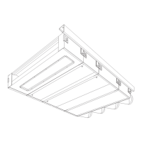
2.6 Suspending the unit
2.6.1 Positioning
- Make sure that the structure from which
the modules are to be suspended can
carry the weight of the whole modular fan
coil unit.
Module weights
PS 20, 21 PS 40, 41 PS 60, 61
PS B
32 kg 51 kg 62 kg
PS P
8 kg 10 kg 12 kg
PS F, FP
10 kg 13 kg 16 kg
PS L
13 kg 16 kg 20 kg
PS G
18 kg 24 kg 31 kg
PS V, VE
15 kg 19 kg 22 kg
- Suspend the unit at a minimum height of
1.8 m.
- Suspend the modules level. This results
in proper venting of the heat exchanger
and (for units with cooling) in proper dis-
charge of condensate.
- Provide for proper sealing if wall or roof
sleeves and the like are installed. Im-
proper installation can cause draught
and condensate problems.
- Ensure the air can flow freely through the
unit’s inlets and outlets.
- Position the unit such that the modules
will be easy to access both during and
after installation.
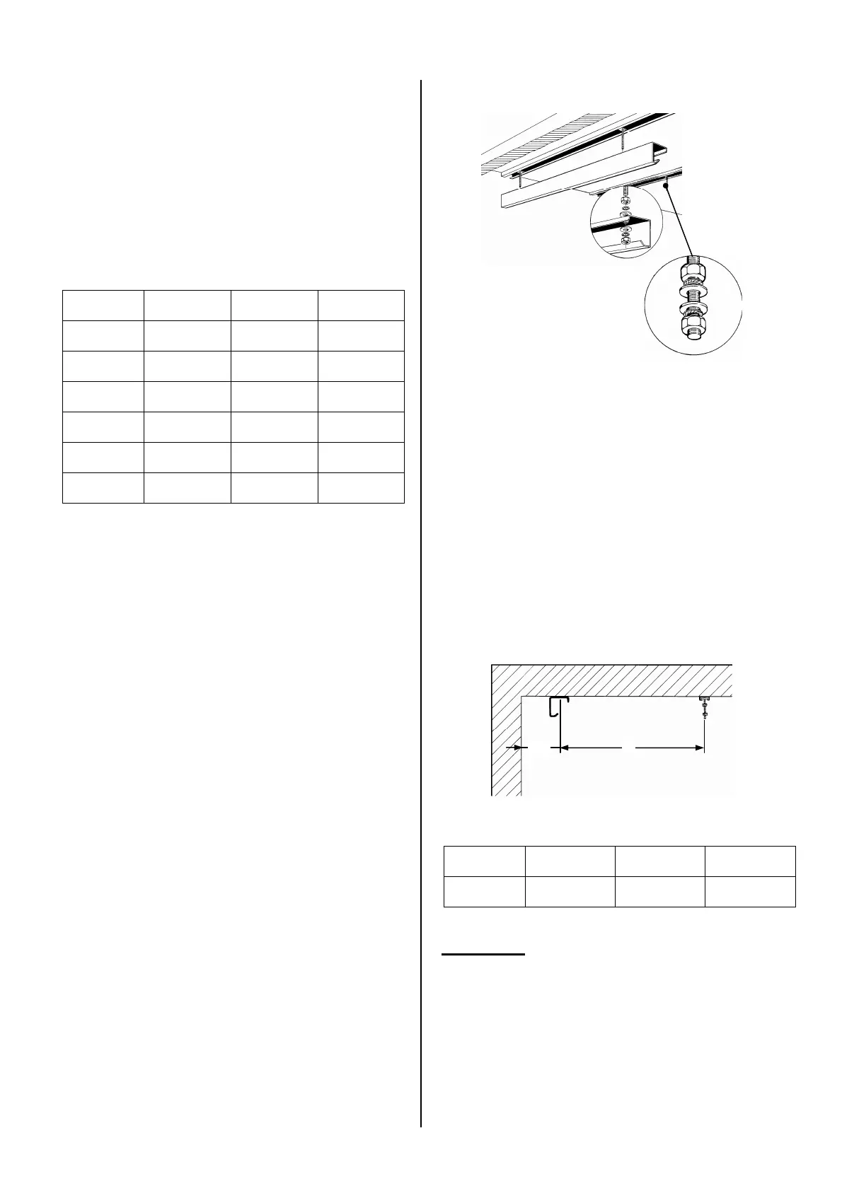
2.6.2 Installing the suspension rail
The modules are hooked into the included
suspension rail n one side. On the opposite
side (connection side), the modules are
suspended from a thread rod. The suspen-
sion rail may either be suspended from a
thread rod 1 (as illustrated above) or be
mounted directly onto the ceiling (as illus-
trated below).
1 Make a suspension structure using
thread rods, mounting rails and the sup-
plied suspension rail. On each thread
rod, apply two nuts at an intermediate
distance of about 4 cm 2.
Centre distance between mounting rails and
suspension rails
PS 20, 21 PS 40, 41 PS 60, 61
A
782 mm 1157 mm 1657 mm
n
Note:
- Keep a minimum distance of 190 mm
between the centre of the suspension rail
and a wall or obstacle, such as a pillar.
This is to allow the modules to be
hooked in.
- Mount the rails in line with a possible
opening for a roof or wall sleeve.
A
190