Modular fan coil unit 2 Installation
Version 2.1 English (17-07-2018)
13
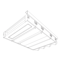
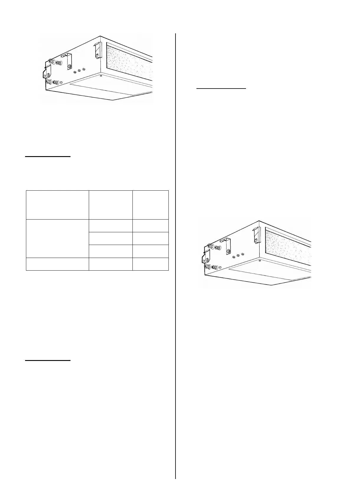
The (1/8") vent cocks 1 are mounted to the
collectors of the heat exchanger, protruding
from the side of the module.
c
Caution:
Biddle recommends the inclusion of a valve
in each pipe.
Operating pressure for CH and CW systems
temperature maximum
operating
pressure
< 20° C 16 bar
< 93° C 10 bar
screwed fittings
< 110° C 6 bar
compression fittings all 3 bar
2.9.2 Frost protection
Only for units with ventilation
Depending on the control system, the unit
has a frost protection thermostat or a control-
ler-integrated protection.
c
Caution:
This reduces the risk of the heat exchanger
freezing but does not warrant 100% protec-
tion.
Prevent the heat exchanger from freezing:
- Provide for constant circulation of the
water at the right temperature.
- Add glycol to the water when the unit is
not in operation during the wintertime.
2.9.3 Connecting water pipes
1 Lay the water pipes, and connect them to
the screwed or compression fittings.
c
Caution:
Tighten the compression fittings well.
2 Fill the CH and/or CW system.
3 Vent the heat exchanger.
4 Check the connections for leaks.
2.10 Connecting the
condensate drain
Only for units with cooling
2.10.1 Particulars
The unit has two (∅ 15mm) condensate wa-
ter drains 2. One of the drains must be fitted
with a stink trap and connected to the sewer.
The second drain is closed with a compres-
sion cap but can be used if necessary.
The unit can be provided with a condensate
drain tray and/or a condensate pump (acces-
sories). If so, their drains must be connected.
2.10.2 Connecting the condensate
drain
1 Install a sewer connection incl. stink trap.
2 Connect the condensate drain tray to a
flexible hose.
3 Connect the hose, with a stink trap, to
the sewer.
4 Insulate the pipes that are not hanging
over the condensate drain tray.