Modular fan coil unit 2 Installation
Version 2.1 English (17-07-2018)
9
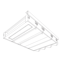
3 Fix the duct sections as you please, e.g.,
by bricking them in or by fixing them with
screws. If using screws, mind their posi-
tions: the screws must not hinder the in-
stallation of the external grille.
n
Note:
Seal any gaps between sleeve and wall in a
draught- and leakage-free manner.
4 Drill the (∅ 5mm) grille fixing holes into
the flanges of the sleeve section that is
fixed to the outer wall.
5 Apply paste onto the inner side of the
grille flanges. The paste is to seal off the
gap between grille and sleeve in a
draught- and leakage-free manner.
6 Fix the grille to the flanges using sheet
metal screws.
c
Caution:
Place the grille with the blades correctly
positioned: oriented outward to allow for run-
off.
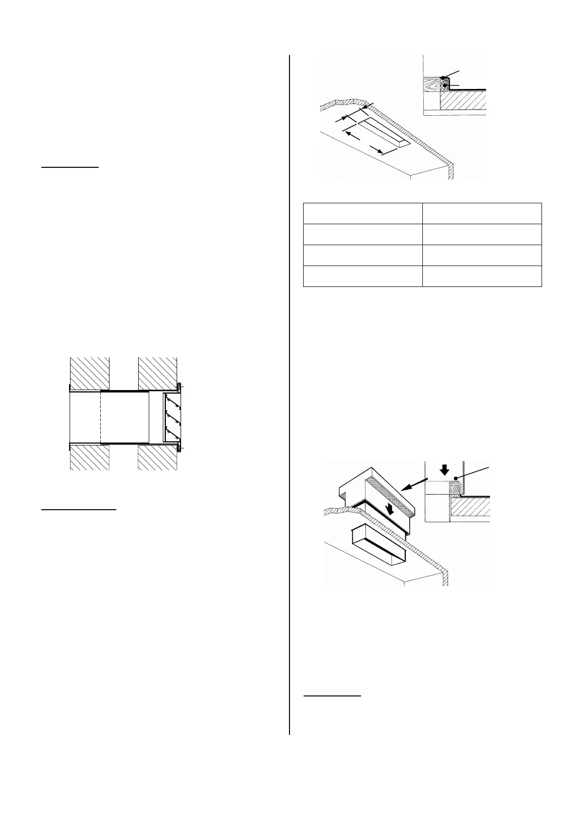
2.5 Installing the roof duct
Accessory, only in combination with air valve
module (PS L)
The roof duct is made up of two parts: a roof
curb and a roof cap. The roof cap consists of
a cover and a sleeve. On delivery, these are
attached to one another.
Opening dimensions for roof duct
type opening, A x B
PS 20, 21
628 x 145 mm
PS 40, 41
1003 x 145 mm
PS 60, 61
1503 x 145 mm
1 Apply the included expanding foam gas-
ket around the ventilation opening of the
air valve module.
2 Make an opening in the roof.
3 Make a water-tight curb 1 around the
opening.
4 Detach the cap from the sleeve. To do
so, loosen the screws in the upper side
of the sleeve.
5 Insert the sleeve into the opening. Con-
nect sleeve and curb by fixing screws 2
through the sleeve’s inner side.
6 Mount the cap to the sleeve.
n
Note:
Seal any gaps between sleeve and roof in a
draught- and leakage-free manner.
A
B
Timber 70x70
Tar mastic
1
2