Do you have a question about the BIG ASS FANS Powerfoil D and is the answer not in the manual?
Ensure power is disconnected to prevent shock or injury during installation.
Installation and wiring must be done by qualified personnel per applicable codes.
Improper installation or use may void the product warranty.
Fans with Ion Technology are suitable for indoor use only.
Complete pre-installation and mounting preparation, then steps 1-5 of the Quick Installation Guide.
Remove hub cover, detach Airfoil Restraint System straps, remove airfoils and winglets.
Use PFX-R static tube if motor frame lacks a weld nut. See kit instructions.
Uninstall existing tube, bracket, and clamp. Replace with PFX-R static tube.
Skip to step 3 if fan has a factory-installed, non-removable static tube.
Install the static tube with retainer clip, torque to 35 ft-lb (47.4 N·m).
Attach the coupler to the static tube, ensuring proper alignment.
Tighten coupler and set screw until snug, but do not over-tighten.
Use shorter white coupler for factory-installed static tubes, taller black for others.
Attach the bracket using 5/16-12 x 1/2" Flange Hex Head Cap Screws.
Verify the long screw on the bracket is inside the slot on the coupler.
Attach the bracket using 10-16 x 1/2" Flange Hex Head Cap Screws.
Verify the long screw on the bracket is inside the slot on the coupler.
Remove VFD cover, route cables through grommet, and connect power supply wiring.
Connect brown wire to F1, blue wire to F2/F3, green wire to PE/GND on VFD.
Remove VFD housing cover, loosen cord grip, and attach quick connect tabs to wires.
Attach 12-10 AWG female quick disconnect terminals to power wires.
Connect Black/Brown to L1, Red/Black to L2/N, White/Gray to L3.
Connect cable with cord grip to static tube cable, routing harnesses between VFD and motor frame.
Install cord grip and nut in back left hole or center hole on VFD housing.
Connect brown wire to L1 and blue wire to L2/N on the power supply.
Reinstall VFD cover and attach lower safety cables to the extension tube.
Connect male wiring harness to airfoil with one bolt hole, female to two bolt holes.
Orient ion generator brushes upward during assembly to prevent damage.
Route cables to exit at the curved, narrow edge of each airfoil and tape them.
Connect power cables to hub bracket harness in front of airfoil edges.
Attach retainers, tighten outer bolts first, then inner bolts.
Secure hub cover using 10-32 x 1/2" Pan Head Screws.
Install controller, ensuring wiring is routed from fan/VFD to the installation location.
| Motor | Direct Drive |
|---|---|
| Weight | Varies by size |
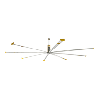
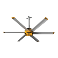
| Material | Aluminum airfoils |
| Diameter | 8 to 24 feet |
| Speed | Variable speed |