Do you have a question about the BIGTREETECH EBB36 CAN V1.1 and is the answer not in the manual?
Initial release of the document.
Correction of pin diagram for heater cartridge port.
Added safety precautions for firmware updates.
Enhanced pin instruction details.
Lists key features of the EBB36 CAN V1.1 board.
Details the technical specifications of the product.
Specifies the supported firmware for the product.
Provides the physical dimensions of the product.
Detailed explanation of the board's pins and their functions.
Explains how to supply power via USB and select power sources.
Details settings for 100K NTC and PT1000 thermistors.
Wiring diagram and instructions for connecting a BL-Touch sensor.
Wiring diagram for filament runout detection.
Wiring guide for RGB LED connections.
Steps to compile the Klipper firmware for the board.
Instructions on how to update the firmware.
Configuration steps for using with BIGTREETECH U2C.
Configuration steps for using with RPI-CAN HAT.
Notes on PT1000 and 100K NTC interface compatibility.
Guidance on CAN bus terminal resistor configuration.
Advice on DIY wiring to prevent damage.
Instructions for USB programming power supply.
Limits on current for heater cartridge and fan interfaces.
Reminder about firmware update precautions.
Details maximum current for heater and fan interfaces.
Troubleshooting steps for firmware update issues via USB.
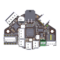
The BIGTREETECH EBB36 CAN V1.1 is a nozzle adapter board specifically designed for 3D printing, particularly for extruders utilizing a 36 stepper motor. This board offers flexible communication options, supporting both USB and CAN bus connections, which significantly simplifies the wiring process for 3D printers.
One of the primary usage features of this board is its firmware update capability. It comes equipped with dedicated BOOT and RESET buttons, allowing users to easily update the firmware via DFU (Device Firmware Upgrade) mode using a USB connection. This ensures that the board can be kept up-to-date with the latest software enhancements and bug fixes.
For enhanced safety and reliability, the EBB36 CAN V1.1 incorporates a protection circuit on the thermistor interface. This circuit is designed to prevent damage to the main control chip that could be caused by electrical leakage from the heater cartridge, a common issue in 3D printing setups. Furthermore, the thermistor interface offers flexibility in selecting the pull-up resistor value via a jumper, making it compatible with various temperature sensors, including PT1000 (with a 2.2K pull-up resistor), which is particularly convenient for DIY enthusiasts who might use different sensor types.
Power management is also a key feature. The USB power supply can be selected through a jumper cap, which effectively isolates the motherboard's DC-DC converter and the USB 5V supply. This isolation helps prevent potential power conflicts and ensures stable operation.
The board provides an I2C interface, which is versatile and can be utilized for various functions beyond its primary purpose. It can be adapted for filament runout or blocking detection, or even for other custom DIY functions, offering expandability for advanced users.
To protect inductive loads such as fans, the EBB36 CAN V1.1 includes follow current diodes on the fan interfaces. These diodes ensure that when the fan MOS (Metal-Oxide-Semiconductor) transistor is turned off, the fan winding current has a continuous path, effectively preventing the generation of high voltage spikes at the MOS tube's drain. This design choice, using a Schottky diode in a SOD-323 package, balances board size considerations with efficient switching characteristics for extruder fans.
Another protective measure is the inclusion of a diode in the DCDC step-down circuit, which is reversely connected. This prevents damage to subsequent circuits in case of reverse connection of the power line, adding a layer of robustness to the board's design.
For precise temperature measurement, the board can optionally integrate a MAX31865 chip. Versions equipped with this chip support both 2-wire and 4-wire PT100/PT1000 sensors, offering high accuracy for temperature readings. The presence of reserved pads for the MAX31865 means that even if a version doesn't initially include it, it could potentially be added later.
Communication flexibility is a significant advantage of this board. It supports both CAN bus and USB communication. The CAN bus option is particularly beneficial for its long data transmission range, strong anti-noise capabilities, robust real-time performance, and high reliability. The CAN bus terminal resistor (120R) can be selected via a jumper cap, and the board also reserves a CAN expansion interface for future connectivity.
To safeguard the USB port from electrostatic discharge (ESD), an ESD protection chip is integrated. This prevents static electricity from damaging the main control chip, enhancing the overall durability of the device. Additionally, the board features a hardware debouncing circuit for limit switches, ensuring reliable and accurate detection of endstop signals.
The EBB36 CAN V1.1 is designed with DIY in mind, providing terminals, female reeds, double-way studs, and screws. This comprehensive set of accessories meets the diverse needs of users who wish to customize or integrate the board into their existing 3D printer setups.
Maintenance features primarily revolve around the ease of firmware updates and the robust protection circuits. The ability to update firmware via DFU mode ensures that the board can be maintained with the latest software, potentially addressing bugs or adding new functionalities. The protection circuits for the thermistor, inductive loads, reverse power connection, and ESD on the USB port contribute to the board's longevity and reduce the likelihood of component failure, thereby simplifying maintenance by minimizing the need for hardware repairs.
When using the board, it's crucial to be aware of certain settings and precautions. For instance, when using a 100K NTC thermistor without the MAX31865 chip, no jumper cap is needed on the TH0 interface, as its pull-up resistor is set to 4.7K. However, for PT1000, a jumper cap must be used to short two specific pins, changing the pull-up resistor to 2.2K. It's important to note that temperature accuracy in this configuration will be less precise than with the MAX31865. For versions with the MAX31865, a DIP switch allows selection between 2-wire or 4-wire PT100/PT1000 sensors.
During firmware updates via DFU mode using the Type-C port, especially when the main power VIN of the hotend is connected, it's critical to disconnect the main power or ensure the update is completed quickly. This is because PA2, which controls the hotend MOSFET, is configured to output a high level in DFU mode, potentially causing the hotend to heat up unintentionally. Prolonged operation in DFU mode with the hotend connected and powered should be avoided.
For CAN communication, if the board acts as a terminal, a jumper cap must be plugged into the 120R position. When performing DIY wiring, it's essential to follow the silkscreen, pin, and schematic diagrams carefully to prevent reverse power connections or accidental connections to the CAN signal, which could damage the module. If there's no external power supply during USB programming, the VUSB pins need to be shorted with a jumper cap to provide working voltage to the module. Finally, the load current for the heater cartridge and fan interfaces must not exceed their maximum withstand current to prevent the MOS tubes from burning out. The total current for the heater cartridge, driver, and fan should not exceed 6A.
| Microcontroller | STM32G0B1 |
|---|---|
| CAN Bus | Yes |
| USB Interface | Type-C |
| Architecture | ARM Cortex-M0+ |
| Logic Voltage | 3.3V |
| Heater Cartridge Output | 1 |
| CNC Fan | 1 |
| Controllable Fan | 1 |
| RGB | 1 |
| GPIO Pins | 16 |
| ADC Channels | 5 |
| Flash Memory | 128KB |
| SRAM | 36KB |
| Clock Speed | 64MHz |
| Communication | CAN |