9
SG3010/SG3015-T3
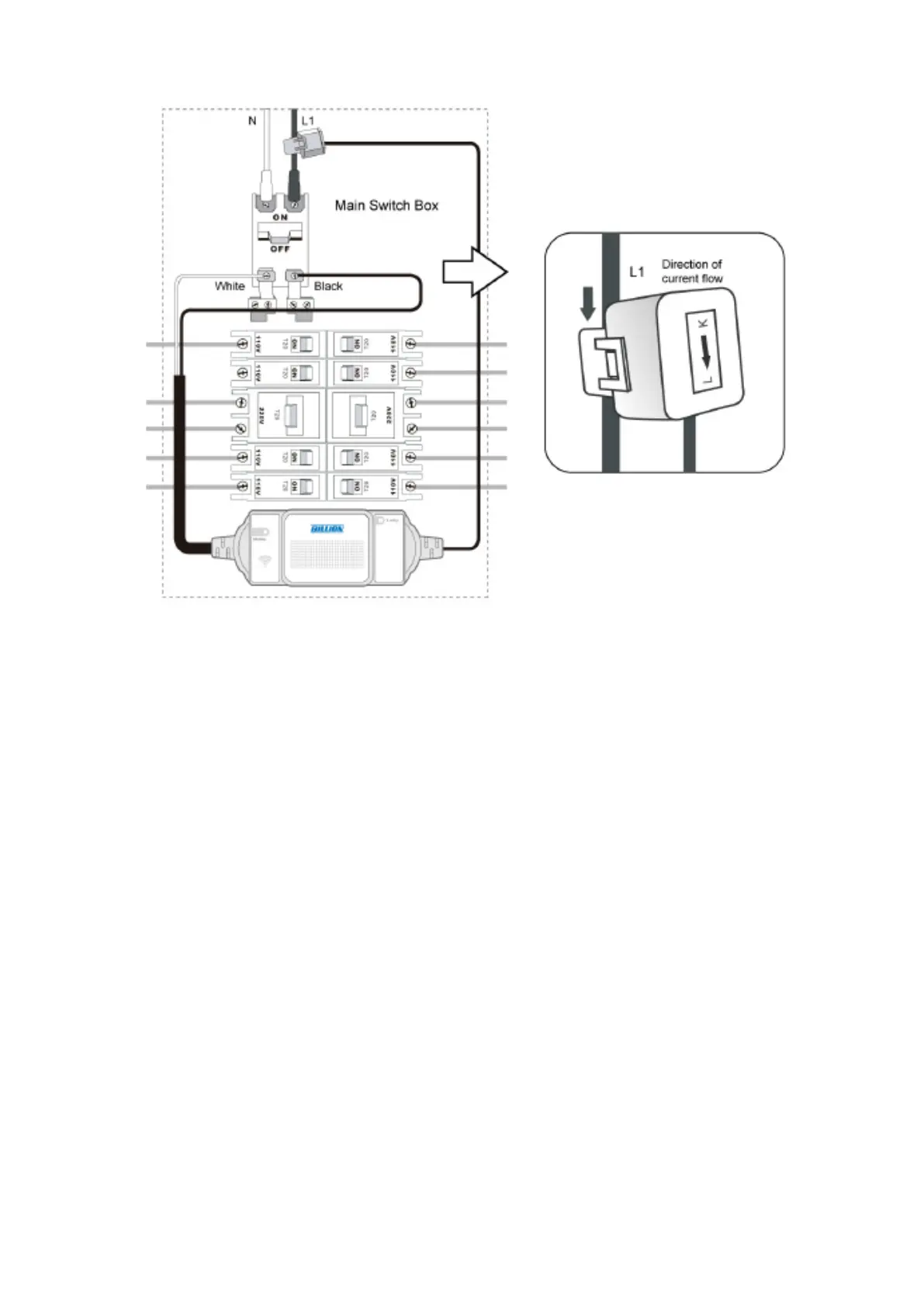
Following the instructed electricity current direction at the bottom of the split-core CT to install the
CT to L1.
1. Following the instructed electricity current direction at the bottom of the split-core CT toin-
stall the CT to L1.
2. Connect the 2 input power ends to the load output terminals of the main switch, the Black
wire to “L1”, and the White wire to ”N”.Please refer to Installation section for detail instruc-
tion information.
3. Set up the connection between SG3015 – T3 and ZigBee Coordinator (Please refer to Net-
working Setup section).
 Loading...