1 2
ON
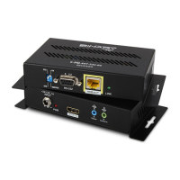
FIGURE 1: Transmitter Layout
A. Thread-locking Power Connector
Connect the included 24VDC,1A power supply
B. Power LED
Lights blue when the unit has power
C. HDMI IN
HDMI Input for connection to a source HDMI output
D. IR Flasher Out
IR output for connection to IR Flasher
E. IR Control In
Connect to the IR output of a control system or IR connecting block to send IR signals to the
remote location. Does not supply power.
F. DIP Switches
DCE/DTE
Select for DTE or DCE mode serial (RS232) communication via DB-9
SERVICE /LINK (RS-232)
Select SERVICE for rmware operation, or LINK for passthrough (normal) operation
G. RS-232
Connect to communicate RS-232 commands when connected to a control system
H. HDBaseT (RJ45 )
Connect to the HDBaseT RJ45 port on receiver
I. Link LED
Lights green when synced with receiver
A B C D E F G H I